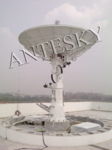
LNB (Low Noise Block Converter) Noise Figure and Selection Guide
1. Antenna Electrical Characteristics
| Item | Description | ||
| S band | X band | ||
| Frequen | Tx: 2.025 – 2.120GHz
Rx: 2.2 – 2.3GHz |
Rx 8.0 – 8.5GHz | |
| Gain(f:GHz) | ≥35.8 +20log(f/2.025) dBi
≥36.5 +20log(f/2.2) dBi |
≥48.0+20log(f/8.0) dBi | |
| G/T (dB/k) at El 5°
(mounted in radome) |
S-band:≥13.5 | X-band:≥25.6 | |
| First Sidelobe | ≤-14dB | ||
| Polarization | RHCP and LHCP | ||
| VSWR (at feed port) | ≤1.3 | ≤1.35 | |
2. Antenna Mechanical Characteristics
| Item | Description |
| Antenna Type | X-Y Geometry |
| Antenna Diameter (m) | 4.2 |
| Mount Type | Limited Motion Antenna |
| Driving Chain | X: DC motor
Y: DC motor |
| Tracking | Program tracking, auto tracking |
| Travel range | X/Y: ±90° |
| Antenna Accessorial Parts and Interface | Hot Dip Galvanise |
| No painting | |
| Foundation Hardware |
3. Antenna Servo Control and Tracking Characteristics
| Item | Description |
| Antenna velocity | up to 5°/s |
| Drive Acceleration | up to 5°/s2 |
4. Antenna Environmental Conditions and Other Features
| Item | Description | Remark |
| Temperature | -40°C~+50°C | |
| Relative Humidity | 0%~100% | |
| Rain | 300mm/h | |
| Wind performance | 67m/s | mounted in radome |
| Others | Packing (sea freight) | |
| Installation | ||
| 12 months warranty | ||
About remote sensing antenna, Antesky also develop below products,
if you are interesting, please contact us through sales@antesky.com
| Item | Description | Frequency band | Pedestal |
|---|---|---|---|
| 1 | 1.8m Fixed Remote Sensing Receiving Antenna System | L-band, X-band, L/X dual-band, S/X dual-band | X/Y Pedestal |
| 2 | 2.4m Fixed Remote Sensing Receiving Antenna System | L-band, X-band, L/X dual-band, S/X dual-band | X/Y Pedestal |
| 3 | 3.0m Fixed Remote Sensing Receiving Antenna System | L-band, X-band, L/X dual-band, S/X dual-band | X/Y Pedestal |
| 4 | 3.7m Fixed Remote Sensing Receiving Antenna System | L-band, X-band, L/X dual-band, S/X dual-band | X/Y Pedestal |
| 5 | 4.2m Fixed Remote Sensing Receiving Antenna System | L-band, X-band, L/X dual-band, S/X dual-band | X/Y Pedestal |
| 6 | 4.5m Fixed Remote Sensing Receiving Antenna System | L-band, X-band, L/X dual-band, S/X dual-band | X/Y Pedestal A-E+T three axis pedestal |
| 7 | 5.2m Fixed Remote Sensing Receiving Antenna System | L-band, X-band, L/X dual-band, S/X dual-band | X/Y Pedestal |
| 8 | 5.4m Fixed Remote Sensing Receiving Antenna System | L-band, X-band, L/X dual-band, S/X dual-band | A-E+T three axis pedestal |
| 9 | 6.2m Fixed Remote Sensing Receiving Antenna System | L-band, X-band, L/X dual-band, S/X dual-band | A-E+T three axis pedestal |
| 10 | 7.3m Fixed Remote Sensing Receiving Antenna System | L-band, X-band, L/X dual-band, S/X dual-band | A-E+T three axis pedestal |
| 11 | 9.0m Fixed Remote Sensing Receiving Antenna System | L-band, X-band, L/X dual-band, S/X dual-band | A-E+T three axis pedestal |
| 12 | 12m Fixed Remote Sensing Receiving Antenna System | L-band, X-band, L/X dual-band, S/X dual-band | A-E+T three axis pedestal |
| 13 | 13m Fixed Remote Sensing Receiving Antenna System | L-band, X-band, L/X dual-band, S/X dual-band | A-E+T three axis pedestal |
Further reading about Antesky S/X Dual Band Antenna for Remote Sensing
Antesky S/X Dual Band Antenna Design Scheme for Remote Sensing
S/X Band Remote Satellite Ground Station
PST Testing for 4.2M S/X Band Antenna
Customer feedback of 4.2m S X dual band antenna from East-Asia
Related posts


