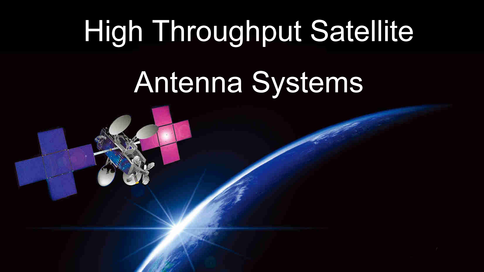
In April 2017, China’s first high-throughput communication satellite, Zhongxing 16 was launched, marking the beginning of HTS.
In the beginning of 2019, it is planned to launch zhongxing 18 satellite, which will further build a high-throughput satellite system and improve the broadband network system.
Zhongxing 18 HTS satellite is a multi-band, multi-beam, multi-functional satellite.Its ka-band multi-beam transponder is an effective complement to zhongxing 16 satellite. Through the coverage of Ka multi-beam in northeast and northwest China through the satellite project of zhongxing 18, the national coverage of the domestic Ka frequency band will be further achieved.
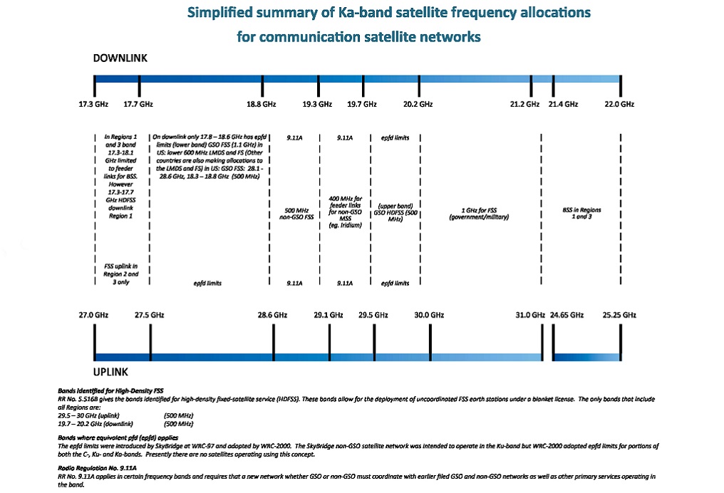
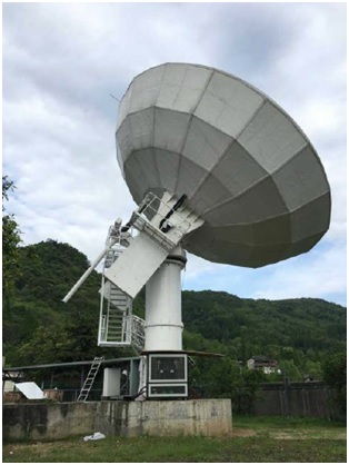
As the research and development unit of China high-throughput satcom ground station antenna system supplier, ANTESKY has successively completed the delivery and use of the 9.0-meter Ka band gateway station antenna in the area corresponding to multiple beams.In addition, ANTESKY participated in the production and development of Brazil telecom HTS 13m Ka band gateway antenna system, and completed the installation and debugging test of gateway station antenna, and the system is now running steadily. ANTESKY has become one of the few manufacturers in the world with the ability to design, produce and deliver ka-band large-diameter antennas.
Model: HTS 13.0M Ka-band Antenna Features:
- High accuracy reflector,High stiffness Az/El THA pedestal
- Sub-reflector and quadripodstructure,Galvanized with white painting
- HVAC system for antenna hub,Large 2m hub with >1m access door
- Calibrated transmit monitor couplers and receive inject couplers for IOT and TT&C
- Dual-speed motor control with gear driven in Azaxis Dual-drive chain for anti-backlash in Azaxis
- Aircraft warning lights,Large access platform with stairway,Lightning Protection,Emergency switches
- A circular polarized Ka-Band cassegrain6-port Tx/Rx feed with TE21 tracking coupler (monopulse) and feed rain blower
- Automatic dehydrator to keep off mositureout the feedlinedry for low loss
HTS 13m Ka-band antenna system
RF Parameters
| No. | Item Description | Specifications |
| 1 | Frequency Rang(GHz)
-Transmit(Tx) -Receive(Rx) |
27.0-30.0
17.8-20.2 |
| 2 | Gain(dB):
Tx(at Tx port of feed) Rx(at Rx port of feed) |
69.1+20lg(f/28.5)dBi
99.2+20lg(f/20.2)dBi |
| 3 | Radiation Pattern: First Sidelobe Wide Angle Sidelobes | -14dB Comply to regulations ITU R-S.580-6 |
| 4 | Half Power Beam width | 0.066° at 30.00GHz
0.099° at 20.2GHz |
| 5 | Polarization | Tx and Rx: RHCP&LHCP
Trk:RHCP/LHCP |
| 6 | Axis Ratio | 1.06 |
| 7 | Isolation(dB)
Rx to Rx Tx to Tx Tx to Rx Rx to Tx |
≥20dB ≥20dB ≥85min ≥85min
|
| 8 | VSWR (at feed port) | Tx and Rx:1.35:1 |
| 9 | Power Handling,W(CW) | 1000W (at Transmit per port), 2000W total |
| 10 | G/T(dB/k) at GHz,EL=20°,Clear Sky and Light Wind(TLNA=150K) | >39.9+20Lgf/19.2dBk |
| 11 | Air Pressure | Max. 1.5PSI,:0.5PSI |
| 12 | Feed Flange
Tx Rx Trk |
WR34
WR42 N type |
| 13 | Feed Insertion Loss | Tx:≤0.5dB Rx:≤0.75dB |
HTS 13m Ka-band antenna system
Structure Parameters
| No. | Item Description | Specifications |
| 1 | Antenna Type | Dual Shaped Cassegrain Antenna |
| 2 | Diameter of Main-reflector(m) | 13M |
| 3 | Surface Accuracy of Main Reflector | ≤0.3mm |
| 4 | Surface Accuracy of Sub-Reflector | ≤0.15mm |
| 5 | Feed: 2Rx/2Tx
Trk: LHCP/RHCP Switchable |
4-port Frequency Circular-Polarzation Feed with TE21 Mode monopulse tracking Coupler |
| 6 | Pedestal Type | Dual-motor with Gear drive in Az Jackscrew driven in EL(Single Motor)
THA, EL/AZ |
| 7 | Antenna Steerability | AZ:220° continuous,
EL:0° to 90° continuous, |
| 8 | De-icing Power rate for main reflector | 50KW(electricity heating, if apply) |
| 9 | HUB Air-conditioning | 10KW(refrigerating capacity) |
| 10 | Environmental Condition
Normal Operation Wind Degraded Operation Wind Survival Wind Temperature Relative Humidity Earthquake Rain Solar Radiation |
50km/h gusting to 72km/h 72km/h gusting to 100km/h 200km/h at EL=90° Outdoor:-40℃ to 50℃ Outdoor:100% 0.3g Horizontal, 0.1g Vertical 100/hr 1.2kw/sqm |
| 11 | Design Life | 20 years |
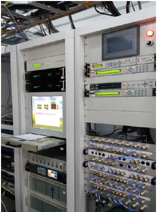
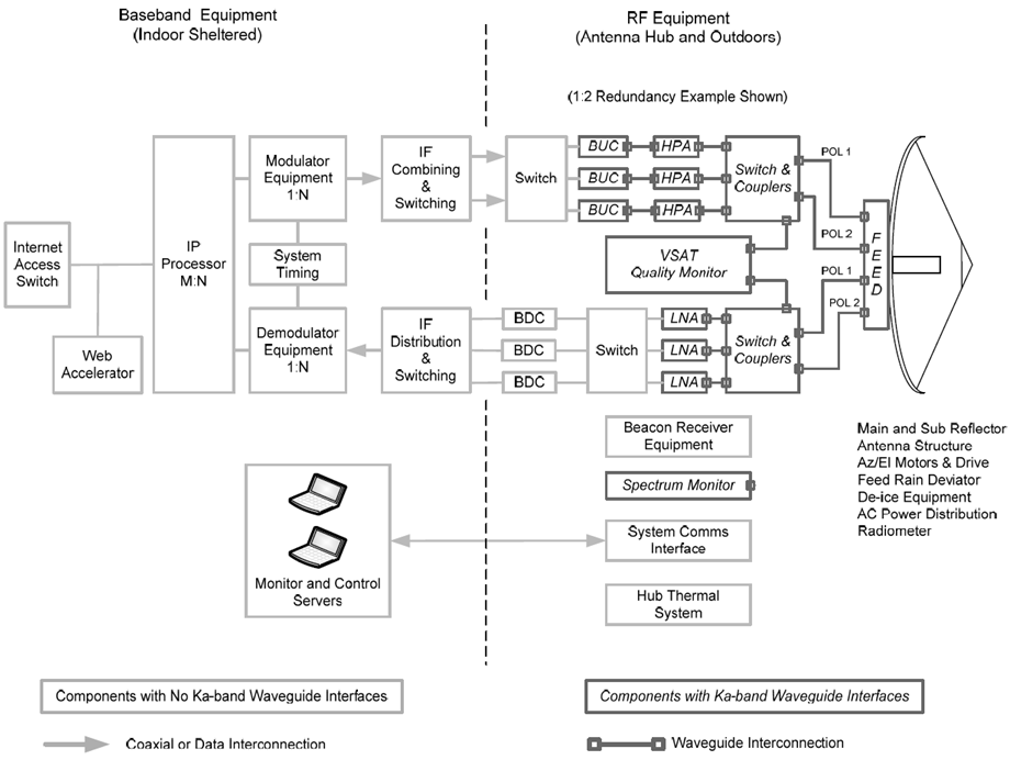
in order to make full use of the EIRP, G/T performance of the Ka satellite feeding beam, intermediate frequency and RF components should be installed in the Antenna Hub of the gateway station as far as possible. This installation method reduces the connection length of the waveguide and coaxial cable, ensures the end-to-end RF signal indicators to the maximum, and facilitates the maintenance and operation of the RF equipment. The BUC is usually installed close to the HPA and connected via Ka band waveguide. The LNA is installed close to the antenna feed port to improve G/T performance at gateway station. To achieve high availability, RF systems are usually redundant, adopting 1:2 redundancy for both uplink and downlink circuits in the examples. Of course, integrated system availability requirements, installation space size and other factors, can also have other different redundant designs.
Most antenna components are located outdoors, including reflectors, antenna supports, elevation and azimuth motors and drive electronics, feed rain deviator system, de-icing system, AC power distribution, radiometer (if required).
Baseband equipment: baseband equipment includes modulation and demodulation equipment, system clock unit, intermediate frequency distribution circuit, reversing switch, gateway station server, and interface equipment between the ground Internet.The common Data Center computer room is suitable for placing the baseband equipment inside the gateway station.
The modulator of the gateway station transmits a DVB-S2 carrier to each spot beam; the demodulator demodulates the TDMA return carrier transmitted from each small station; the clock unit provides a clock signal to the modulator and demodulator of the gateway station, thereby Keep the whole network station and the gateway station in clock synchronization, and each station will perform TDMA bursts at the most precise time.
Some servers in gateway stations perform IP data processing and Web acceleration functions. IP processing functions allocate satellite bandwidth to small stations, and Web acceleration compensates for the long transmission delay caused by the distance between the satellite and geosynchronous orbit to improve the user’s Internet browsing experience. Gateway stations are connected to ISP access points via optical fiber and then incorporated into Internet backbone network. The fast flow of data between servers, modulators, and demodulators at gateway stations is achieved through high-end switches.
All power distribution units, switching units, data and IF interface devices, modulators, demodulators, clock distribution units, and servers in a gateway are redundant configurations, and the entire gateway will not be interrupted by a single point of failure.
