1. Overview of 2.4m Ka band Flyaway Antenna
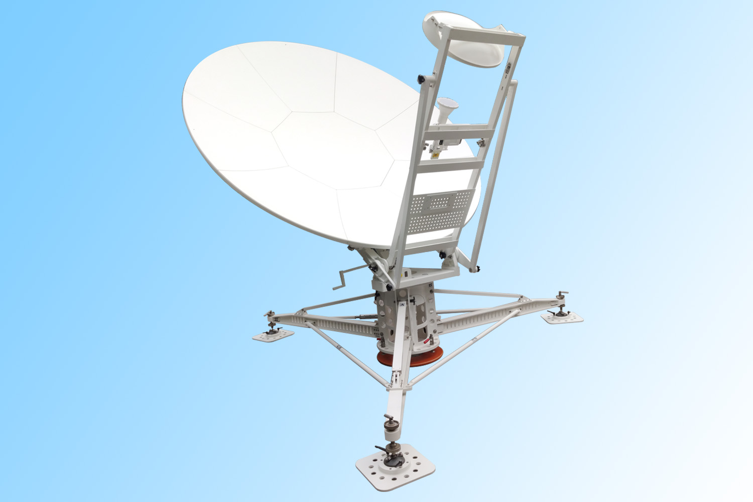
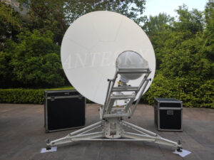
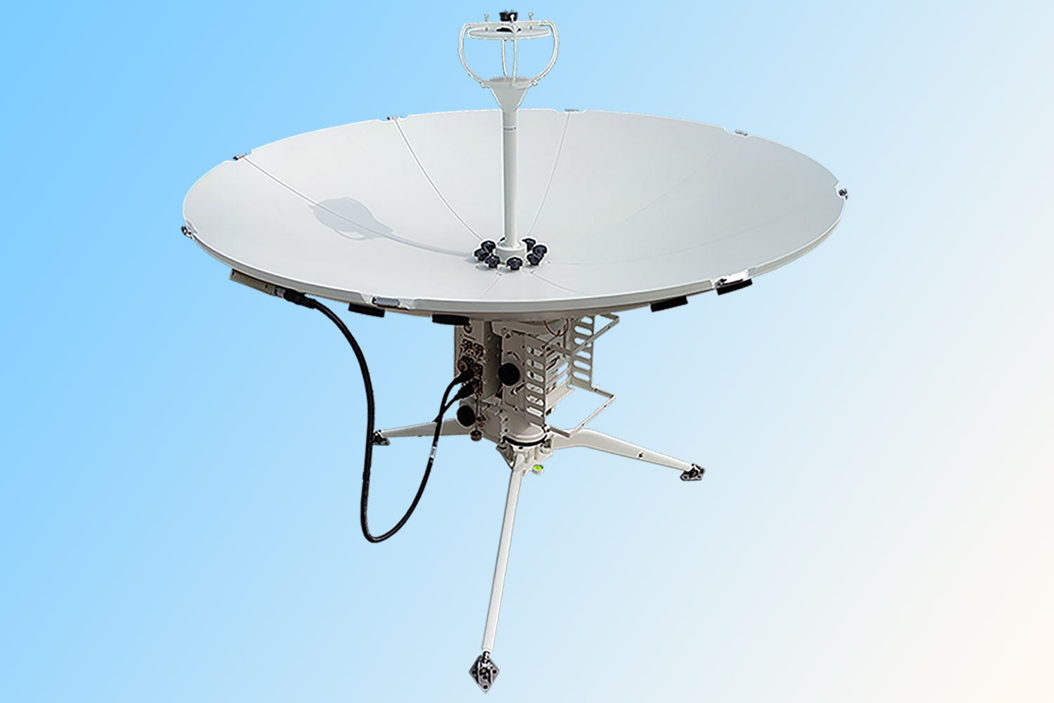
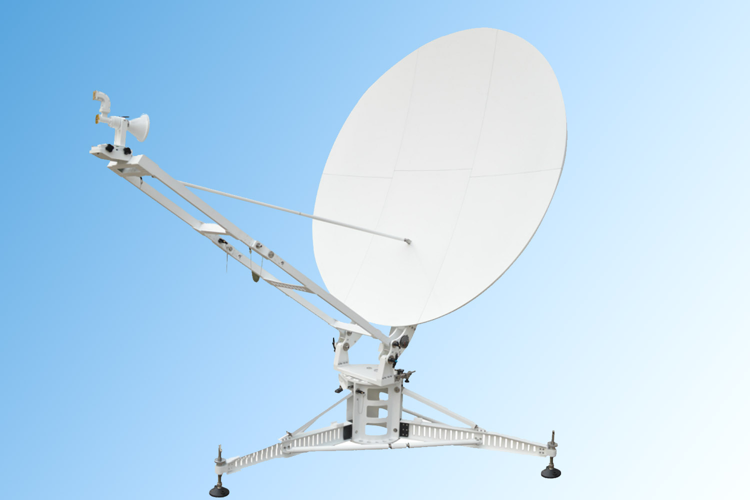
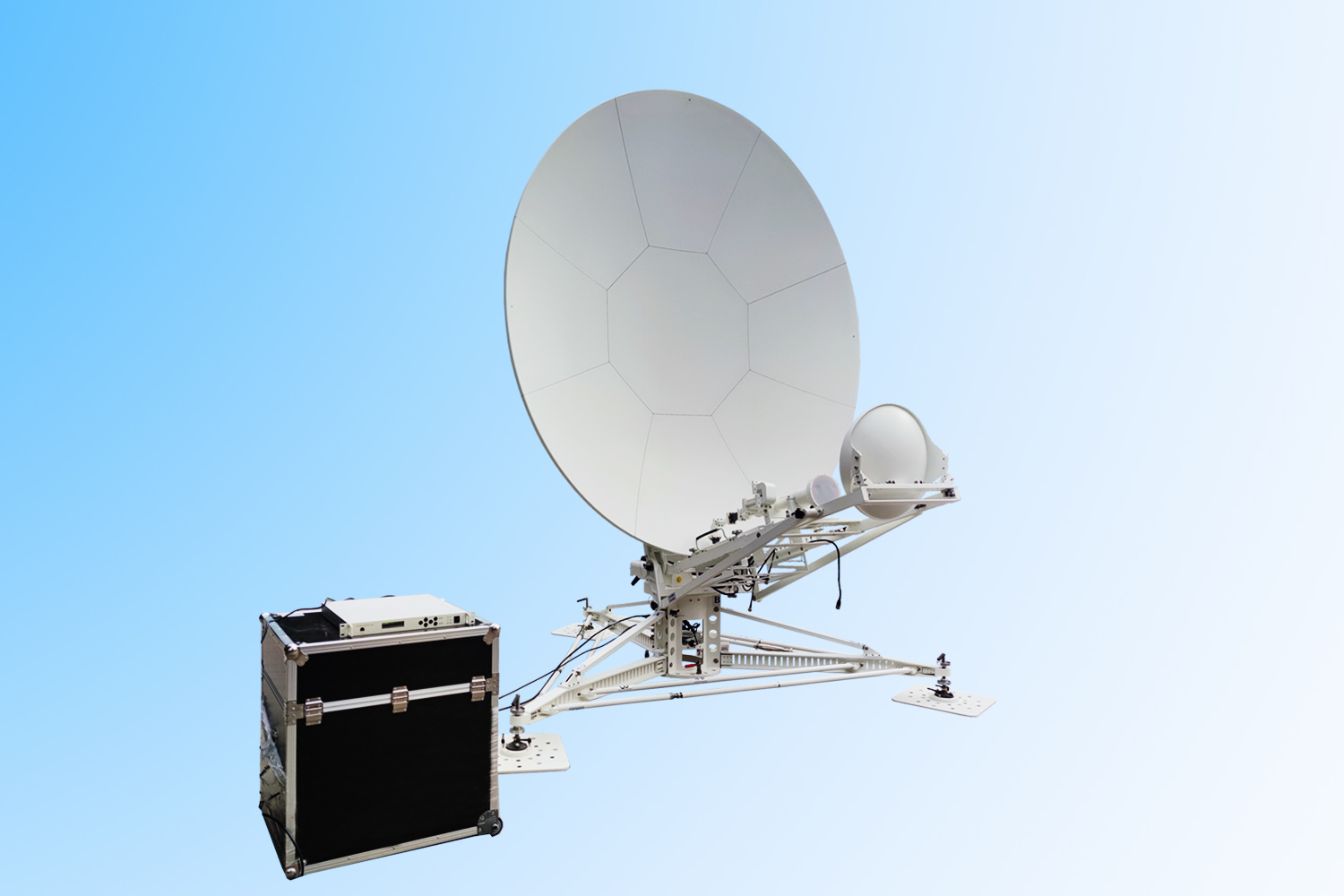
ATCF-240KA 2.4M ka band manual flyaway antenna from Antesky is newly launched and in great demand for customer who requires receive and transmit signal in emergency communication. Our antenna can meet the requirements of CCIR 580-6 , ASIASAT and INTELSAT.
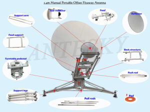
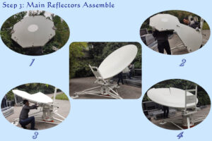
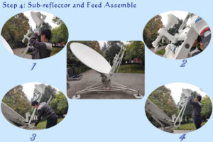
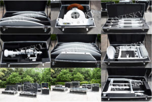
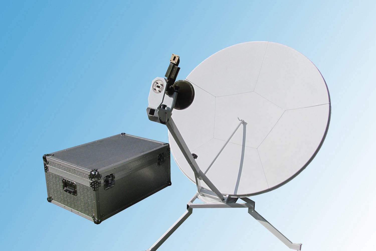
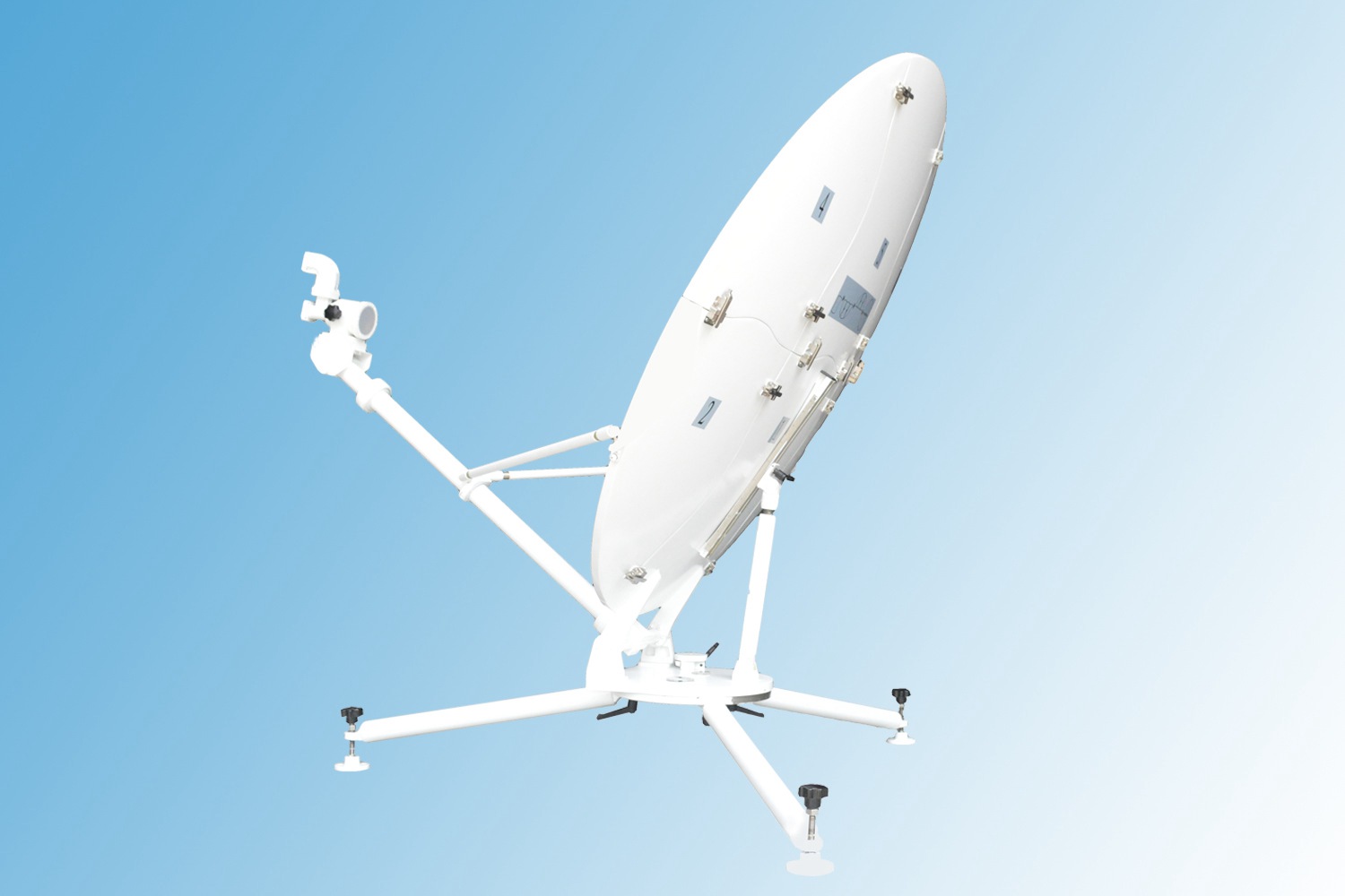
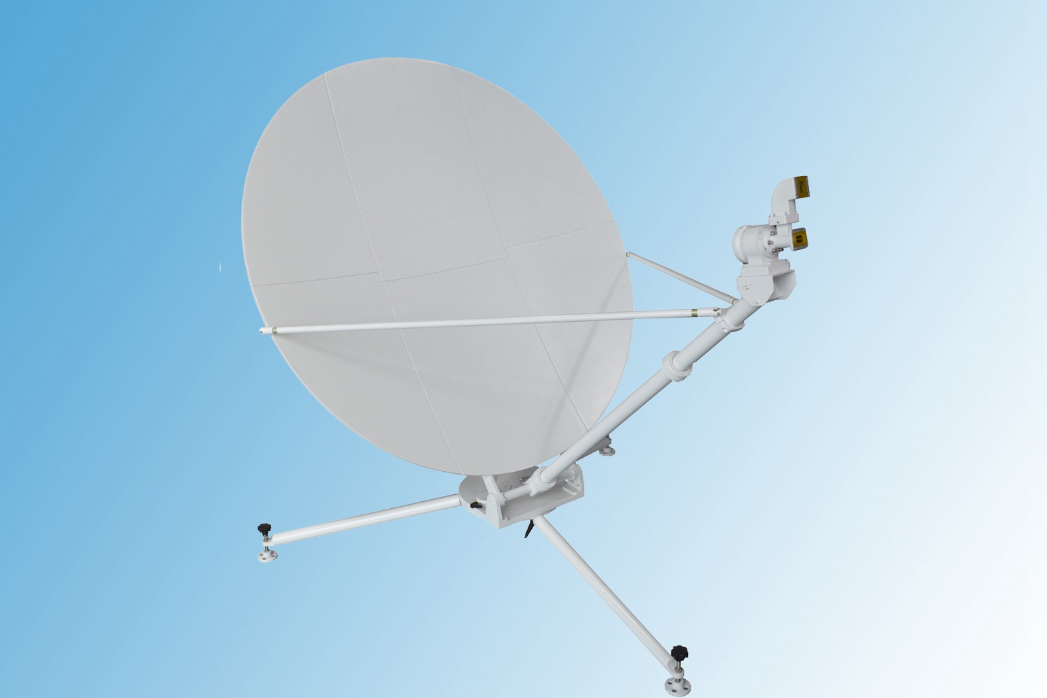
This 2.4m ka band manual flyaway antenna completed antenna system includs reflectors, pedestal structure and feed network. Panel is made up of more than 90% carbon fiber composite material with light weight and high surface accuracy of 0.3 RMS. Antenna backup support structures and turntable pedestal are made of special materials with high stiffness. This compact structure can ensure the strength under the heavy wind condition. The dual-reflector feed structure is updated to realize quick installation and replacement with excellent electrical performance. Meanwhile, the 9 petals of panels can be installed repeatedly with high precision. Two persons can finish installation within 20 minutes and no tools required. The whole system can be packed in customized rigid aviation cases with moveable wheels for easier carry.
2.4m ka band manual flyaway antenna is widely used in temporary or frequently changing installation sites, or in where no regular communication means on the ground like in earthquake disaster relief, TV broadcasting, maritime affairs, exploration, meteorology and other emergency communication fields as easy to carry and quick deploy. This 2.4m manual flyaway antenna supports multimedia service like voice, data, audio and video, and wide area network access in a limited time.
2. Key features of 2.4m ka band manual flyaway antenna
- Meet the requirements of CCIR 580-6, ASIASAT and INTELSAT;
- Panel using the latest carbon fiber composite material for light weight;
- Easily and quickly deploy without any tools;
- No tools required during installation and two persons can complete installation within 20 minutes;
- Dual-reflector and offset feed design for high gain and excellent sidelobe performance;
- Packed in 7 rigid customized cases with moveable wheels;
- Optional aviation package material available.
3. Technical specification of 2.4m ka band manual flyaway antenna
|
2.4 M FLYAWAY ANTENNA SPECIFICATION |
|||
| Model | ATCF240KA | ||
| Diameter | 2.4m | ||
| Operating Frequency, GHz | Ka-Band | ||
| Receive | Transmit | ||
| 17.7~21.2 | 27.5~31 | ||
| Gain, Mid-band, dBi | ≥51.0+20lg(f/20) | ≥54.5+20lg(f/30) | |
| Polarization | Circular(4 Port) | ||
| XPD (on Axis), dB | / | ||
| Axial Ratio | ≤ 2dB | ||
| VSWR | 1.30 | 1.30 | |
| Tx. Power Capability, W | / | 300 | |
| Feed Interface | WR42 | WR28 | |
| Isolation, Tx to Rx, dB | ≥85 | ||
| Rx toTx, dB | ≥40 | ||
| First Sidelobe | ≤ -14dB | ||
|
Mechanical Specification |
|||
| Antenna Type | Offset | ||
| Surface Accuracy(R.M.S.) | ≤0.3mm | ||
| Azimuth | 0°~360° | ||
| Elevation | 10°~90° | ||
| Polarization | ±90° | ||
|
Environmental Specification |
|||
| Operational Wind | ≤11 m/s (ballasting) | ||
| Survival Wind | ≤18 m/s (ballasting) | ||
| Operating temperature | -40°C~+55 °C | ||
| Storage temperature | -50°C~+70 °C | ||
| IP grade | IP 65 | ||
| Humidity | Not more than 95% (20 °C) | ||
|
OPTIONS |
|||
| Finishes Color
Green, tan or per customer demand |
Frequency available
Ka-band,Ku band,C band |
Drive mode
Manual or motorized |
|
5. Assemble guidance of 2.4m ka band flyaway antenna
Find a level ground site (flyaway antenna with no requirements for the foundation). Firstly, check the components according to the provided packing list. If there found no any lost or damage, then take out the components respectively to start assembling.
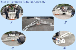
1. Turntable and three support legs and support rods assemble
Put pedestal on the ground and then insert three lags into an arbitrary groove on the rotating pedestal and connect the pin. After installation, then aim the upper hole of pull rod to the pins of adjacent two support legs and then insert.
For more installation details , please click for installation video of 2.4m manual flyaway antenna.
6. Package & shipping dimension of 2.4m flyaway antenna Manufacturer
- Packing List
Box No. Description DIM(L×W×H)MM G.W(KG) N.W.(KG) 7-1 Back Structure Worm Gear Push Rod
Support Arm
1625*950*400 81 36 7-2 Support Legs Pull-Rod A
Pull-Rod B
1805*700*400 85 45 7-3 Feed 1065*500*570 36 12 7-4 Turntable Pedestal Ground Plate
Manual Handhold
815*650*828 81 51 7-5 Reflector (BDFH) 1170*560*973 54 16 7-6 Reflector (CGAE) Central Reflector
1145*660*1125 75 26 7-7 Ground Anchor Ground Anchor Plate
Support Arm (Upside)
Support Arm (Downside)
1345*743*630 78.4 35.4 Total 7 3.99CBM 528.5 221.4
- Package details
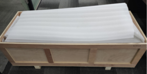
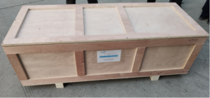
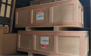
-Inner packed with customized carbon fiber aviation case
-The outer packing is plywood box to prevent damage or vibration during transportation.
8. Learn more about 2.4m carbon fiber flyaway antenna System

