LEO is an orbit around the Earth, which is at least 1000km above the Earth’s surface and has an orbital period of about 84-127 minutes. Objects below about 160 km (99 miles) will experience very fast orbital attenuation and height loss. The traditional commercial satellite is the GEO satellite which are fixed on the GEO belt and move as the Earth rotates. It is located far from the Earth (must be greater than LEO). In fact, this satellites can cover a larger area of land and water. The emergence of constellations such as Iridium (66 satellites), TELEDESIC (228 satellites), Skybridge (80 satellites) and Globalstar (48 satellites) suggests that LEO constellation may be the basis for future two-way wireless communication systems. This possibility makes the tracking of LEO satellites an important issue for the today’s earth stations designers. Remote sensing is popular for LEO satellite.
Tracking LEO satellites in the S/X band presents us with new challenges in the design and manufacture of earth stations.Only the fastest and most expensive azimuth-elevation pedestals are able to track LEO satellites on high elevation passes continuously. The problem appears when the satellite approaches and leaves from its highest elevation. In this way, the pedestal must make high speed azimuth movements in order to track the satellite. Insufficient azimuth speed can lead to the earth station being unable to track the satellite continuously for passes that exceed a particular maximum elevation.
Many solutions have been provided to solve this problem, including trajectory optimization where the antenna trajectory is modified to minimize antenna pointing losses on or near zenith passes. However, the narrow beam width excludes the use of this technique. Other methods include the use of either an azimuth-elevation-tilt pedestal or an X-Y pedestal. Both two pedestals allow zenith pass tracking.
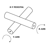
Take the X-Y pedestal as example as below:
As shown above, an X-Y pedestal has two orthogonal axes: the first is a horizontal fixed primary axis; the second is perpendicular to and mounted on top of the first axis. This configuration allows the pedestal to provide zenith pass tracking even with the use of relatively low speed motors. An X-Y pedestal design offers several advantages over its azimuth-elevation-tilt and azimuth-elevation counterparts.
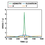
For the X-Y pedestal design, the angular velocity required for two axes remains in a very small range, with the exception of the minimum height of the satellite channel. This condition is not the case for an azimuth-elevation pedestal where the required angular velocity in azimuth increases rapidly as the maximum elevation of a satellite pass approaches 90°. For an overhead pass of a LEO satellite with an 800 km orbit, the maximum angular velocity required by either axis is only a fraction of a degree per second. This low velocity produces improved pointing accuracy compared to the three-axis system where the angular velocity required is significantly higher. Another advantage is that the X and Y axes are identical, which means that the required spare parts can be kept to a minimum.Additionally, the pedestal can be built from high quality, off-the-self components, which allow economical designs to be constructed for a wide range of operating conditions and antenna sizes. Off-the-self components also has low cost maintenance. The X-Y pedestal uses brushless DC motors, which eliminate the need for expensive rotary joints and slip rings.Finally, the X-Y pedestal is a low cost solution where the simplicity of the design compared to a three-axis pedestal increases at the same between failures.
Hope all info above can be helpful and interesting. For more info, please email to sales@antesky.com


