1. General
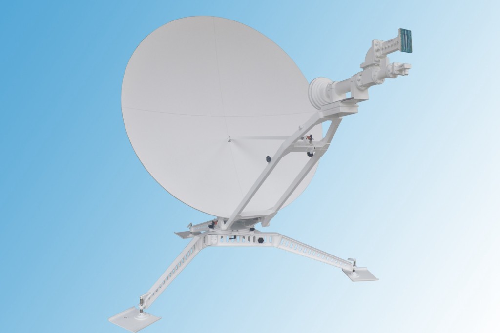
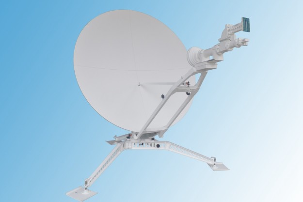
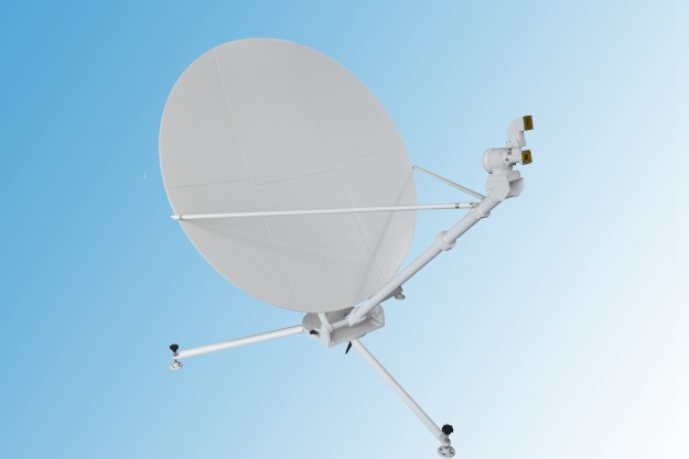
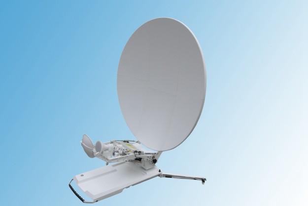
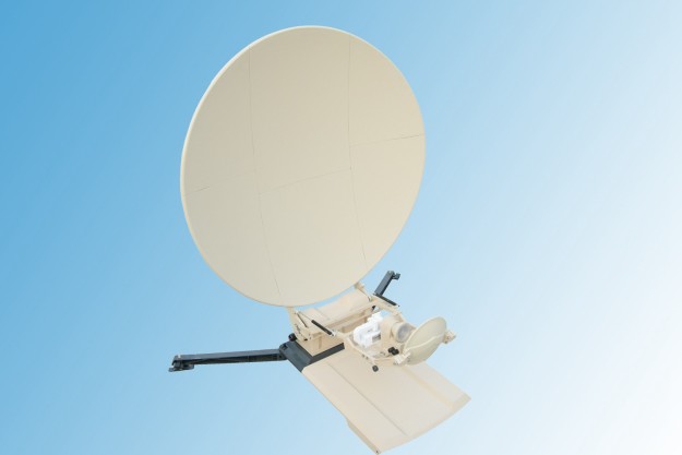
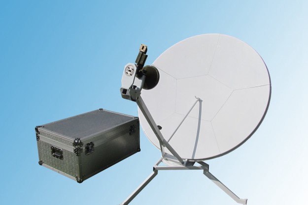
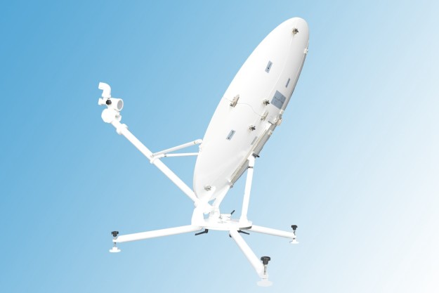
Flyaway antenna is of offset antenna, which is comprised of reflector, feed system, azimuth adjusting mechanism, pitch adjusting mechanism and triangular pedestal.
The antenna is packed in a backpack which can be loaded in automobile like jeep.
2. Structural Characteristic
2. Structural Characteristic
(1) Flyaway Antenna Structure Characteristic
In order to embody portable performance, make sure the flyaway antenna characteristics of light weight, small geometry size in package, quick and convenient assembly, high precision of reassembly in the design.
In order to reduce flyaway antenna weight, carbon fiber composite material is adopted in the reflector. The reason is the carbon fiber composite materials possess characteristics of light weight, high modulus, and a low coefficient of thermal expansion. There are various structures to make flyaway antenna reflector with carbon fiber. And honeycomb sandwich construction is widely adopted because of high rigidity, light weight and convenient manufacture. Flyaway antenna adopts honeycomb sandwich construction with aluminum. Carbon fiber itself possesses conductivity, but not as well as metal. Carbon fiber becomes poor conductor because resin exists basically. So the flyaway antenna reflector needs metallization. Method of metal ion transference is introduced to metallize the portable antenna. The shape of flyaway antenna reflector is optimized in design, and the geometric dimension is reduced so as to pack conveniently. The eternal outline of the flyaway antenna reflector is quadrilateral, which consists of four 350*350 small quadrilateral reflector. The illustrated diagram of flyaway antenna panel is shown in Fig 3-43.

There are location and fast connection device between all block panels to make sure of quick assembly and high precision reassembly. And there needs no tool when assembling. The weight of flyaway antenna reflector is less than or equal to 7kg.
(2) Flyaway Antenna Feed system
The feed system is composed of feed source and duplexer, mounted on the feed pedestal. The feed pedestal is fixed on the bottom of main reflector locating face, complementary with rod to ensure the correct position of feed source.
As shown in Fig3-44, loosen the locking device of feed source, and rotate duplexer. In the way it can adjust the polarization.

The feed strut is ¢45mm2mm aluminum alloy tube with BJ-120 aluminum waveguide passing through the middle. To ensure correct connecting of waveguide, all waveguide ends of joint are non-standard joint, as shown in Fig 3-45.

The length of struts is 531mm and root connector is 59mm to ensure compactness of package.(the part is fixed on the flyaway antenna and not dismounted).
The whole support structure (including horn, duplexer, rotary joint, strut waveguide, etc.) weighs 1.8kg.
It is simple and reliable to connect feed strut and root. Insert one end and point the other to locating pin, hitch to straight knurl nut of strut and then lock. There is waveguide flange on the other end of connector. Connect bend waveguide to power amplifier of the backside flyaway antenna (This section is fixed and not removed).
It is simple and reliable to connect feed strut and root. Insert one end and point the other to locating pin, hitch to straight knurl nut of strut and then lock. There is waveguide flange on the other end of connector. Connect bend waveguide to power amplifier of the backside flyaway antenna (This section is fixed and not removed).
The complete feed system has 2 flange(one with90 scale) supporting on panel of feed strut. When adjusting, loosen flange screw with scale, rotate duplexer in place, and then lock the screw.
(3)Flyaway antenna pedestal structure
The flyaway antenna pedestal consists of azimuth adjusting device, pitch adjusting device and strut leg. The weight is 6.5kg. Each part of flyaway antenna pedestal can be demounted manually, loaded in bags, and removed and repaired by one person. When assembling flyaway antenna, take parts out from box and assemble manually. Three groups of pedestal support can choose reinforcement and wind-resistance measurement. Nail individually on three foot drives. Or press a sandbag on each strut to fasten fixed pedestal and adjust torsion bar to keep pedestal in horizontal level.Azimuth adjusting mechanism
Azimuth adjusting device mainly consists of azimuth turntable, star screw. When roughly adjusting, adjust triangle support. When fine adjusting, loosen star screw and drive azimuth turntable and then can adjust antennas azimuth angle (-0~30). Lock star screw in the time of locking
Elevation adjusting mechanism
The mechanism is lead screw adjusting. One end is fastened on pedestal; the other end is connected with flyaway antenna reflector. When adjusting El, press knurl tightly and lock jacking block of screw to adjust in a wide range. And then loose jacking block, rotate knurl nut to adjust fine. The pitch range is between 15~50°when using lead screw. The El adjusting mechanism is shown in Fig3-46.

About Antesky
Antesky Science Technology Inc. is specially engaged in designing, manufacturing and installing satellite communication antennas and relevant servo equipments. We can offer a complete line of earth station antenna products and systems, such as Satellite communication antennas, Earth Station Antenna, Vsat antenna,TV receive only antennas, satellite news gathering Antennas, Flyaway antenna, control system and tracking system.
Related posts

