Ka dual-channel LNA&BDC system amplifies the input Ka-band broadband signal with LNA and divides it into two channels for down-conversion to L-band. This integrated system combines advanced components to deliver superior signal reception, distribution, and processing capabilities in the Ka-band frequency range (approximately 17.2GHz ~ 22.3GHz). Here are the key features and benefits of this innovative cost-effective system.
- System components of Ka Band Dual-Channel LNA&BDC System
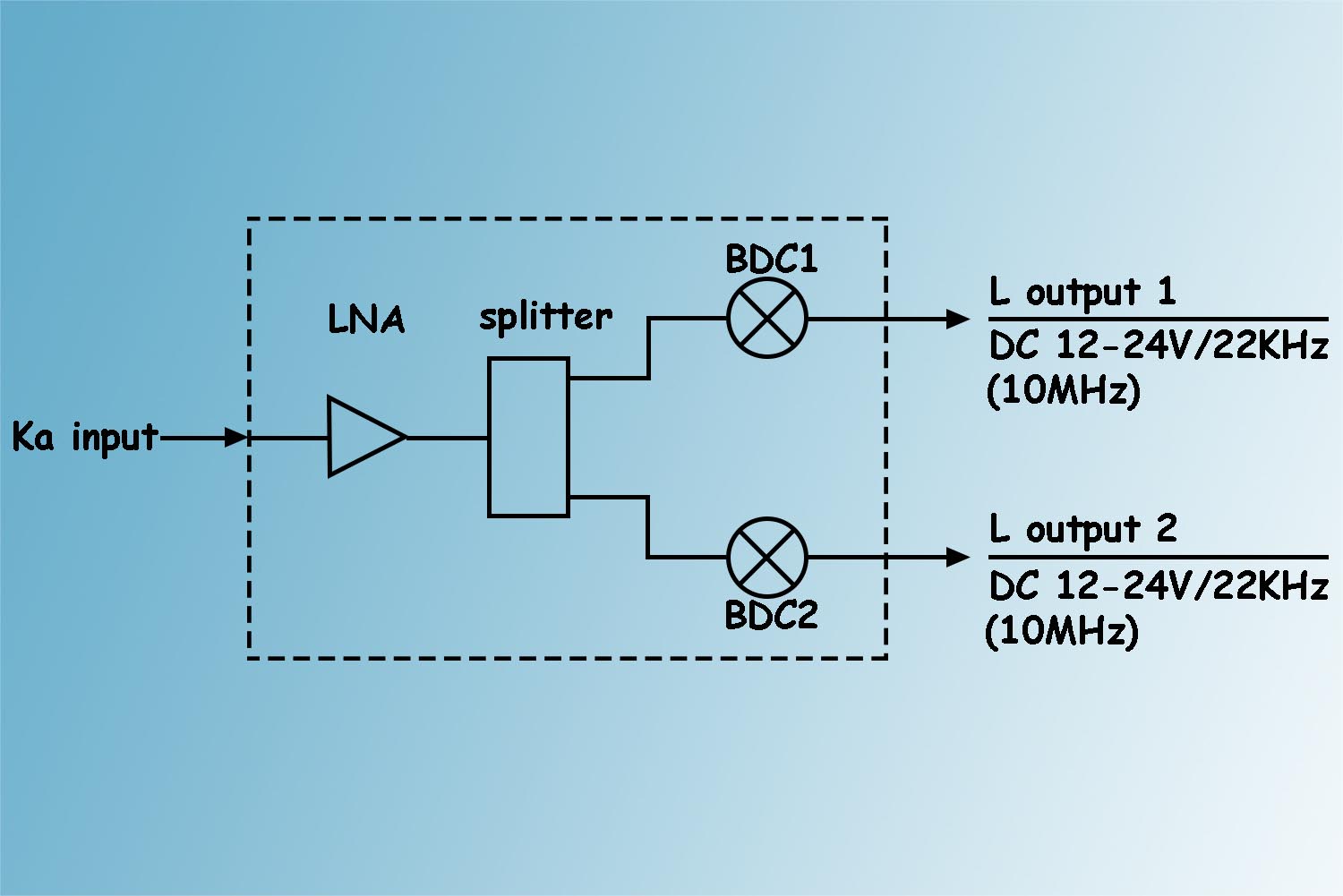
This Ka Band Dual-Channel LNA&BDC System consists of one Ka band low noise amplifier (LNA) , one power splitter , two block downconverters (BDC), which is a comprehensive solution tailored for high-frequency communication, radar, and sensing applications.
- Ka-band Low Noise Amplifier (LNA):Our Ka-band LNA offers exceptional low-noise performance, amplifying incoming signals with minimal added noise. This ensures high sensitivity and improved signal-to-noise ratio (SNR), critical for capturing weak signals and maximizing detection range in Ka-band applications.
- Power Splitter:The integrated power splitter enables efficient distribution of amplified signals to multiple downstream components or channels. With precision signal splitting, it facilitates parallel processing or multi-channel operation, enhancing system flexibility and scalability.
- Dual Block Downconverters (BDCs):The system includes two block downconverters, each optimized for Ka-band frequencies, capable of converting high-frequency RF signals to lower intermediate frequencies (IFs). The dual-channel configuration supports simultaneous processing of two independent signals or channels, increasing system throughput and efficiency.
- Schematic block diagram of Ka Band Dual-Channel LNA&BDC System
Figure 1 Diagram of Ka Band Dual-Channel LNA BDC System
3. Functional featuresof Ka Band Dual-Channel LNA&BDC System
- Wide Frequency Coverage: Designed specifically for the Ka-band frequency range, this system offers comprehensive coverage suitable for a variety of Ka-band applications, including satellite communication, remote sensing, and radar systems. It ensures reliable performance and compatibility with Ka-band transmission standards.
- Customizable Configuration: The modular design of the system allows for easy customization and expansion to meet specific application requirements. Additional LNAs, power splitters, or BDCs can be integrated as needed, offering flexibility and adaptability to diverse system architectures.
- Compact and Rugged Construction: Built for reliability in both laboratory and field environments, the system features a compact and ruggedized construction. It is engineered to withstand harsh operating conditions while maintaining optimal performance and longevity.
- Improve system stability and reduce costs :The integrated Ka Band Dual-Channel LNA&BDC System integrates LNA, power splitter & BDC System, combining them to form a closer whole. This tightness increases the stability of the system. The integrated system can share, process and store more efficiently, and it is also more convenient to configure, install and debug the system. Since various parts can be shared, redundant and duplicate equipment is reduced. This reduces the cost of the entire system.
- Improved production efficiency and product quality: Ka Band dual-channel LNA&BDC System integration can standardize and automate the production process, thus improving production efficiency. Production personnel can more easily conduct production testing and system maintenance, reducing the waste of human and material resources. Various parts can be combined and tested and inspected to ensure the stability and reliability of the system. Integrated software and hardware can better cooperate and adapt, thereby improving product quality and performance.
4. Main electrical indicators of Ka Band Dual-Channel LNA&BDC System
a) RF input frequency: 17.2GHz ~ 22.3GHz;
b) IF output frequency: 950MHz~2150MHz;
c) Noise temperature: 170K;
d) Gain: 63dB;
e) Gain flatness: ≤±1.5dB/each frequency band;
f) P1dB output power: ≥+10dBm;
g) Third-order intermodulation: ≤-25dBc (P1dB backoff 3dB);
h) Port VSWR: RF input:≤1.35:1,
IF output : ≤1.5:1;
i) Frequency stability: When using internal reference, frequency stability is ±1ppm;
External reference 10MHz, 0±5dBm, co-multiplexed with the IF output interface;
Support internal and external reference adaptation;
j) Phase noise: ≤-60dBc/Hz@100Hz;
≤-70dBc/Hz@1kHz;
≤-80dBc/Hz@10kHz;
≤-90dBc/Hz@100kHz;
k) Power supply: DC 12~24V, fed through the IFoutput interface;
l) Local oscillator control:
| No. | Frequency band
switching control |
RF frequency | IF frequency | LO. frequency |
| band 1 | 13V | 17.2-18GHz | 950-1750MHz | 16.25GHz |
| band 2 | 13V+22KHz | 17.85-18.65GHz | 950-1750MHz | 16.9GHz |
| band 3 | 15V | 18.5-19.3GHz | 950-1750MHz | 17.55GHz |
| band 4 | 15V+22KHz | 19.15-19.95GHz | 950-1750MHz | 18.2GHz |
| band 5 | 18V | 19.8-20.6GHz | 950-1750MHz | 18.85GHz |
| band 6 | 18V+22KHz | 20.45-21.25GHz | 950-1750MHz | 19.5GHz |
| band 7 | 22V | 21.1-21.9GHz | 950-1750MHz | 20.15GHz |
| band 8 | 22V+22KHz | 21.75-22.3GHz | 950-1500MHz | 20.8GHz |
5.System interface and others of Ka Band Dual-Channel LNA&BDC System
a) RF input: FBM220 (WR-42G);
b) IF output 1: N-50K (IF output, external reference and power supply/22K input);
c) IF output 2: N-50K (IF output, external reference and power supply/22K input).
6.Environmental characteristics of Ka Band Dual-Channel LNA&BDC System
a) Working temperature: -40℃~+60℃;
b) Storage temperature: -40℃~+70℃.
Above is the brief introduction of Ka Band Dual-Channel LNA&BDC System. Welcome to inquiry us if you are interested in this system. Our email sales@antesky.com.


