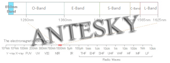
Frequency Band used for Weather Satellite Receiving System include L-band, C-band, Ku-band and Ka-band etc.
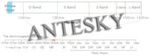
The diagram of communication wavelength bands is shown below:
L-Band (1-2 GHz)
As a relatively low frequency, the L-band is easier to handle, requires less complex and inexpensive RF devices, and because of the wider beam width, the antenna’s pointing accuracy does not have to be as accurate as a higher band. Only a small fraction (1.3-1.7GHz) of the L-band is allocated to satellite communications on INMARSAT. Inmarsat uses the L-band for its fleet broadband, Inmarsat-B and C.
The old Inmarsat A and B antennas are typically 1 meters in diameter, but with the launch of more powerful satellites and the use of maneuverable point beams, the new Fleet broadband antenna drops to less than 30 cm (12 inches). The L-band is also used for low-Earth orbit satellites, military satellites and terrestrial wireless connections, such as GSM mobile phones. It is also used as an intermediate frequency for satellite television, where the Ku or Ka band signal is converted to the L band at the antenna LNB to make it easier to transfer from the antenna to the lower deck or indoor equipment. Because the L-band does not have much bandwidth available, it is an expensive commodity. L-Band (long band: 1565-1625 nm) is the second low loss band, which is a popular choice when using C-band is not enough to meet bandwidth requirements. The same WDM and EDFA technologies can be applied to the L-band.
C-Band (4-8 GHz)
The C-band transmit frequency is usually around 6 GHz and the receiving frequency is about 4 GHz. It is suitable for large (2.4-3.7 m) antennas. The C-band is typically used for large ships that cross the ocean on a regular basis and requires uninterrupted, dedicated, always connected connections when they move from one area to another. Routes are usually rented on a full-time satellite bandwidth segment provided to the ship, providing access to the Internet, a public telephone network and a data return connection to its headquarters. The C-band is also used for ground microwave links, which can occur when ships enter ports and interfere with critical ground links. This can lead to severe restrictions within 300 km of the coast, so it is required to close the terminal as it approaches land.
Ku-Band (12-18 GHz)
The Ku-band refers to the lower part of the K-band. “U” comes from the German term and refers to “under” while “a” in Ka-Band refers to the “top” or top of the K-Band. The Ku-band is most commonly used in satellite television and is currently used in most VSAT systems on yachts and ships.
Ku-band has more bandwidth available, so the C or L bands are less expensive. The main drawback of Ku-Band is that the rain fades. The wavelength of the raindrops is consistent with the wavelength of the Ku-band, causing the signal to decay during the shower.This can be overcome by transferring additional power, but of course it also brings costs.
Because of the narrower beam width, the antenna’s pointing accuracy needs to be closer than the L-band, so the terminal needs to be more precise and expensive. The Ku-band coverage is generally covered by a regional point beam, covering television reception in the main land area.
The movement of VSAT vessels from one area to another requires a change in the satellite beam, sometimes without coverage between the beams.
Ka-Band (26.5-40 GHz)
Ka-Band is a very high frequency that requires high pointing accuracy and complex RF equipment. Like the Ku-band, it is susceptible to rain. It is usually used for HD satellite TV.
It is also now used for ground VSAT services. Ka band bandwidth is plentiful and, once implemented, should be quite cheap compared to the Ku-band.
Weather Satellite Receiving System mainly adopts AZ/EL type pedestal
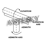
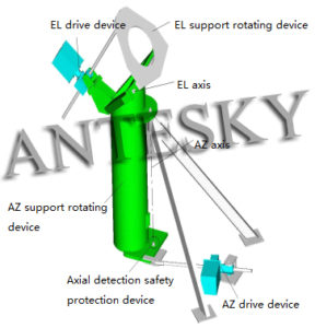
The antenna mount is a device that supports the antenna structure and moves the antenna within a prescribed airspace. It moves the antenna according to a predetermined rule through the antenna control system, or follows the target motion; and accurately measures the orientation of the target through the axial position detecting device.AZ/EL type pedestal antenna mount has three basic types including vertical axis type, rotary table and wheel-rail type.
①Vertical axis antenna mount
The antenna and the azimuth rotating portion are supported by a vertical axis (azimuth axis). Most of the small and medium-sized antennas use this type of frame, and its basic structure is simple, and it is convenient to design, manufacture and maintain.
②rotary table antenna mount
The antenna and azimuth rotating parts are supported by extra large rolling bearings or hydrostatic bearings capable of withstanding axial loads, radial loads and overturning moments. This type has large bearing capacity, good rigidity, high precision, small axial dimension, low center of gravity and good stability, and is usually used for large and medium-sized antennas.
③wheel-rail type
The antenna and the azimuth rotating portion are supported by rollers and rails. The track diameter is generally 1/2 to 2/3 of the antenna diameter, and the roller and track are also the final drive of the azimuth drive system. The roller and track are frictional drives, so the azimuth drive capability is determined not only by the power of the drive motor, but also by the static friction between the drive roller and the track. In order to ensure the driving ability of the azimuth, there must be sufficient positive pressure and friction coefficient between the wheel and rail, so it is generally used for large antennas. The truss structure is trussed, and the large azimuth bearing, the azimuth large gear and the large turret are omitted compared with the first two types. Therefore, the structure is simple, the ratio of the weight to the caliber is small, the cost is low, the installation and maintenance are convenient, and the high structural precision can be achieved. A disadvantage of the pitch-orientation antenna mount is that there is a blind spot near the zenith that does not track the target. When the target passes near the zenith of the antenna, the required azimuth tracking angular velocity tends to infinity, so it can only track targets below a certain elevation angle. If continuous tracking is required, additional models must be used.
The azimuth cylinder and the elevation triangular support structure used in the 7.3m l-band antenna are welded by thick steel plates. The azimuth cylinder is welded with a steel plate and has a diameter of 720 mm. The upper and lower side welding shaft seats of the azimuth cylinder are respectively connected with the azimuth upper and lower shaft heads, and the bottom large flat plate is connected with the azimuth bearing and the azimuth screw to realize the azimuth rotation, and the azimuth rotation is divided into two equal sectors, all of which are 100 mm. Bearings are mounted on the upper and lower shaft heads to ensure flexible rotation. The azimuth shaft head is equipped with an azimuth shaft angle detecting device and a limiting device. The tilting right axis head is equipped with a shaft angle detecting device and a tilt limit device. When the antenna moves to the limit position, the micro switch operates, the power source is cut off, and the antenna stops rotating to ensure the safety of the device.
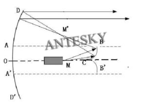
Ring focus antenna is made up of reflector, sub-reflector and feed horn as shown below:
The main reflector is a partial rotating paraboloid, and the sub-reflector is constituted by an elliptical arc CB rotating around the main reflector axis OC, and the feeding horn is located at a focus M of the rotating ellipsoid. The electric wave radiated from the feed is reflected by the sub-reflecting surface and converges on the other focus M’ of the ellipsoidal surface. M’ is the focal point of the paraboloid OD. Therefore, the electric wave reflected by the main reflecting surface is emitted in parallel. Since the antenna is a rotating body about the mechanical axis, the focus M’ constitutes a circular ring perpendicular to the antenna axis, so the antenna is called a cyclo-focus antenna.
Ring focus antenna advantages
- The feed is installed in a place where the reflection field of the sub-reflecting is not irradiated, thereby eliminating the influence of the reflection field of the sub-reflecting surface on the performance of the feed, reducing the voltage standing wave ratio of the antenna, and obtaining good cross-polarization characteristics;
- The distance between the feed horn and the secondary reflector is relatively close, and the diameter of the secondary reflector surface can be selected to be small, which reduces the occlusion of the secondary reflector facing the aperture of the antenna, improves the antenna efficiency, and reduces the antenna side lobes;
- Large angle angle feed horn can be used to make the feed system structure more compact.
Ring focus antenna design
In order to obtain a better oral field distribution, the main and sub-reflector of the ring-focus antenna are shaped to meet the requirements, so as to improve the efficiency of the ring-focus antenna. The shaping of the main and secondary reflecting surfaces of the ring-focus antenna is optimized according to three conditions: the law of conservation of energy, the law of reflection of the primary and secondary reflecting surfaces, and the equal optical path conditions.
In order to reduce the sidelobe level, the following measures are taken: selecting the appropriate sub-reflecting surface and sub-reflecting surface edge irradiation level to reduce the first sidelobe level and the side of the secondary reflecting surface to diffract and leak; selecting the tire-type aperture field distribution function To reduce the far side lobes.

