As we all know, when the satellite earth station is newly built, expanded and updated, the network access verification test is required. According to the satellite network management convention given by the satellite company, we can see that the network access verification test mainly includes the following four parts for reference. This time we focus on the content of this part of the user earth station network access verification test.
01 Content of Satellite Company’s Network Management Protocol
02 Verification test on earth station antenna access to network
03 User service carrier opening
04 Operating requirements of user service carrier
1.Satellite Company’s Network Management Protocol
In order to ensure the safe and reliable operation of user services, the satellite company will formulate the Satellite Network Management Protocol, which specifies the requirements that must be met before and during the operation of satellite earth station user services. Management regulations mainly include the following aspects:
- Complete the network access verification application, that is, complete the user information collection form (such information as business type, network structure, communication system and working mode, geographic location, equipment specifications and models, and relevant test reports)
- According to the requirements, complete the user earth station network access verification test: antenna system performance test, station equipment performance test. Then obtain network access permission.
- Complete the user carrier opening test according to the requirements of the satellite company.
- Formal operation requirements of user carrier.
2. User earth station antenna access verification test
2.1 Why does the earth station need network access verification test
- Avoid interfering with or being interfered by adjacent satellites
- Avoid interfering with the communication of other users on the satellite
- Ensure that the user’s own network can work normally
- Make satellite operators provide better services to users
2.2 When do network access verification test
- After the user creates a new system
- After expansion and transformation of user system
- After the user changes the system related equipment
2.3 Content and scope of network access verification test
It is divided into two parts: antenna system performance test and station equipment performance test.
2.3.1 Antenna system performance test: test of antenna transmission pattern, transmission gain, cross polarization isolation, etc.
- Mandatory requirements for transmitting side lobe
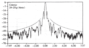
90% side lobe peak gain of main polarization and cross polarization transmitting antennas shall not exceed the following envelope requirements. The peak sidelobe gain beyond the envelope shall not be higher than the envelope by 3dB (this requirement is based on ITU – RS.580-6 and 465-5)
G= 29-25log( θ) dBi
1°*≤ θ ≤ 20 ° (along GS0 direction),
-3°≤ θ ≤ 3 ° (deviation from GSO direction);
*When D/ λ less than 100, this angle should be 100 λ/ D degrees. Where, D is the antenna diameter (m); λ Is the wavelength (m); θ Is the angle away from the axis of the central beam; G is the antenna side lobe gain. The first side lobe shall be less than 14dB lower than the main lobe. The side lobe characteristic test diagram of the transmitting antenna is shown in Figure 1.
Fig.1 Transmitting side lobe pattern
- Transmission antenna gain test
The user can give the transmission gain index of its antenna, but must accurately measure the actual gain, or at least accurately calculate based on the measurement. The gain can be accurately calculated using the method of 3dB point beam width.
Step 1: find out the measurement results of 3dB point beam width in AZ and EL directions.
The second step is to calculate the transmission gain with the following formula:
GT=K/( α AZ* α EL)
GT=transmission gain of antenna under test
α AZ: angle of 3 dB beam width in AZ direction, unit:
α EL: angle of 3 dB beam width in EL direction, in degrees
K is a factor between 23000 and 31000, which depends on the value of the efficiency factor. The Business Operation Center will determine the value of K according to the actual situation.
- Receive sidelobe
In order to prevent interference from other earth stations or satellite networks, the receiving side lobe gain of the earth station antenna should also be limited, but it is not a mandatory requirement.
The receiving side lobe characteristics of the antenna are the same as the transmitting side lobe characteristics.
- Antenna polarization mode
The polarization mode of satellite communication earth station shall be set correctly during network access test and link opening test. For the earth station antenna that can access multiple satellite networks, the polarization of the antenna shall be re calibrated every time the satellite network is changed to ensure accurate polarization.
- Cross polarization isolation
Adjust the polarization of the transmission antenna so that the cross polarization component within 1dB below the peak value of the transmission main lobe gain of any distribution port is at least 30dB lower than the main polarization component. The cross polarization isolation of the earth station receiving antenna shall also meet the above requirements, but it is not a mandatory indicator.
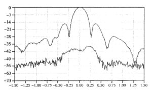
The cross polarization isolation requirement of the transmitting antenna is: when the antenna is linearly polarized, the cross polarization isolation of the antenna in the axial direction is>33dB. In circular polarization, the elliptical axis ratio when the antenna points to the satellite should be less than 1.06, that is, the isolation should be 30.7dB. The transmission antenna cross polarization test diagram is shown in Fig. 2.
Fig. 2 Cross polarization test diagram
- Polarization angle adjustment capability
The satellite communication earth station shall be equipped with a feed system that can rotate easily to change the antenna polarization.
For 4-port (two transmitters and two receivers) feed system, the polarization rotation angle shall be adjustable within ± 25 ° at least.
For 2-port (one transmitting and one receiving) feed system, the polarization rotation angle shall be adjustable within 45 ° at least.
2.3.2 Performance test of equipment in the station is mainly including tests of five indicators, including stray characteristics, modulation characteristics, intermodulation characteristics, power stability and frequency stability. At the same time, we also have certain requirements for the transmission carrier.
- Stray and intermodulation test
The purpose of this test is to determine any stray signal (excluding intermodulation products) EIRP radiated by the antenna from the uplink system of the earth station in the satellite working band, except for the carrier signal. These spurious signals mainly reflect carrier independent noise and carrier related parasitic signals in the earth station uplink system.
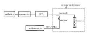
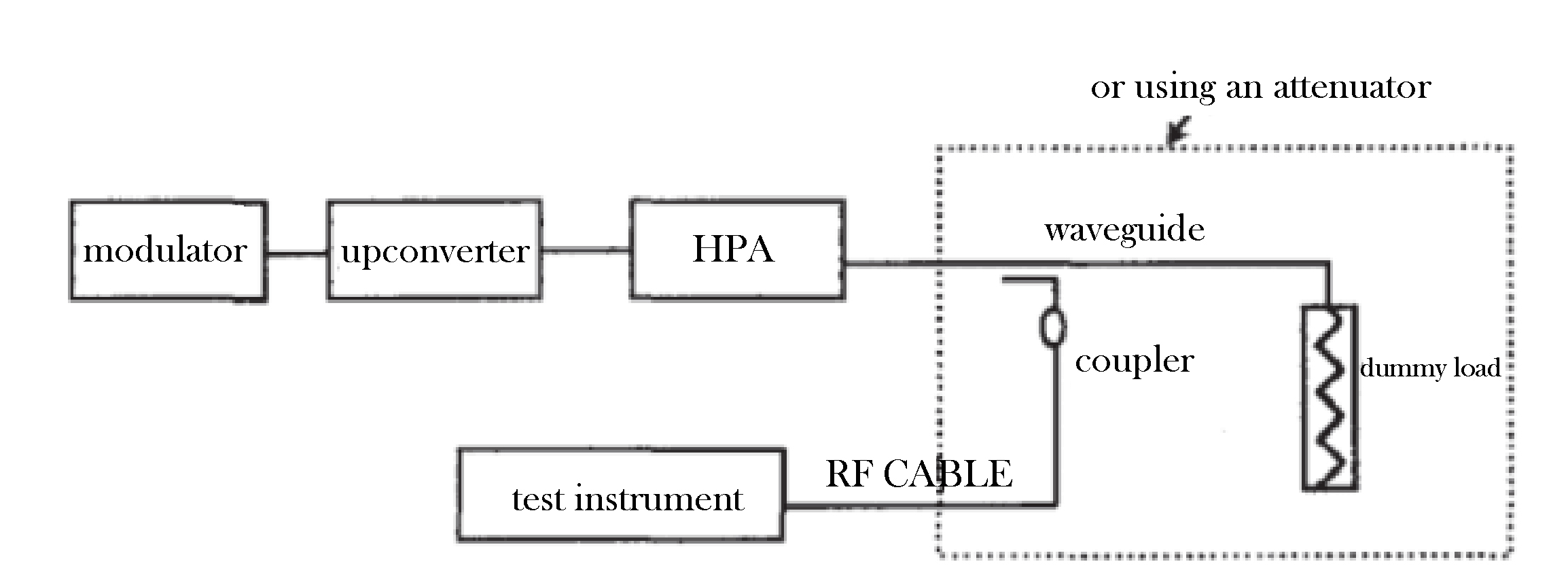
The available equipment and test connection diagram are as follows Fig.3:
Fig.3 Equipment and test connection diagram
- Stray test
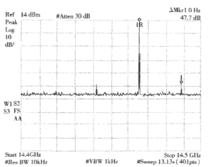
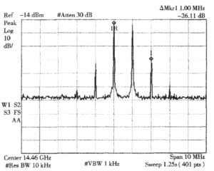
Requirements: The uplink EIRP spectral density of stray products unrelated to carrier modulation shall not be greater than 4dBw/4kHz. The relative level of the spurious products related to carrier modulation and the reference unmodulated carrier should not be greater than – 55dBc+IPBO dB (IPBO is the total return of satellite input of all carriers of the earth station being measured). The stray characteristic test diagram is shown in Figure 4.
Fig. 4 The stray characteristic test diagram
- Modulability test
The modulation characteristic test mainly refers to the in band flatness (flatness of the in band spectrum of the modulation signal corresponding to different code streams), output spectrum (spectrum shaping of the RF modulation signal output by the uplink system) and amplitude frequency characteristic test conducted by the uplink equipment after modulating the carrier. The test includes all uplink devices from the IF output of the modulator to the RF output of the high power amplifier. It is the main item of the uplink system network access test.
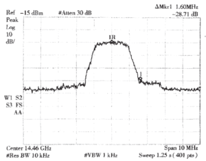
Requirements: the 20dB bandwidth of the modulated carrier shall not be greater than the carrier allocation bandwidth, and the difference between the peak value of the modulated carrier and the spectrum regeneration noise base shall be greater than 26dB. The modulation characteristic test diagram is shown in Figure 5.
Fig. 5 The modulation characteristic test diagram
- Transmission carrier power stability
Uplink power stability refers to the power stability of the earth station uplink system output from the modulator to the power amplifier, excluding antenna gain stability, antenna tracking error, antenna pointing error, etc. The uplink power stability is related to the stability of the modulator output level, the stability of the up converter gain, the stability of the power amplifier gain and other factors. It is the root mean square value of the stability of each device (excluding the antenna) in the uplink system. The stability of the uplink power level of the earth station is closely related to the stability of the EIRP, and its quality is directly related to the stability of the EIRP. Therefore, this item must be tested during the uplink system network access test. The test diagram is shown below Figure 6.
Fig. 6 The inter modulation characteristic test diagram
- Requirements for transmission carrier
It is suggested that satellite communication earth stations have convenient monitoring means to monitor the transmitted carrier strength and carrier frequency value; The satellite communication earth station shall have the function of adjusting the transmission carrier frequency, and shall have the function of disabling transmission and Ku band uplink carrier power control.
- Guidance on the activation of the carrier of user services
The satellite company will guide users to complete the earth station carrier opening. The service carrier opening test mainly includes the following five aspects:
3.1 Antenna aligning to the satellite;
Users should adjust the antenna by themselves to ensure that the antenna is pointing correctly.
3.2 Antenna polarization adjustment;
-The user conducts transmission polarization isolation test at the specified frequency, and the transmission polarization isolation of the antenna under test is ≥ 30dB.
-Temporary business can be appropriately relaxed.
-Provide test spectrum diagram according to user requirements.
-After the test, the user shall turn off the single carrier used for the test.
3.3 Antenna power calibration;
-The satellite company directs the user to adjust the transmission power of the modulated wave.
-After the user carrier power reaches the specified value, the user carrier transmission power can be appropriately adjusted according to the actual acceptance of the user. The user’s receiving Eb/No and transmitting power shall be recorded.
3.4 Modulation characteristic test;
-The user transmits the modulated carrier at the allocated frequency.
-The satellite company determines whether the frequency, bandwidth and modulation mode of the carrier meet the requirements.
3.5 Communication quality test
The bit error rate is mainly tested by the user
4.User service carrier operation requirements
-The user shall use the equipment and transmission signals according to the technical parameters and status of the contract, network access test and opening test calibration when the user carrier is officially running;
-For the replacement or transformation of the transmission equipment, the adjustment of the transmission power, frequency and modulation characteristics shall be applied to Satellite Company in advance and can only be carried out after approval.
-In case of interference or unexpected abnormal events in business operation, the user shall cooperate with the satellite company in interference troubleshooting and emergency handling, carefully check the equipment as required, and assist in finding the cause; If necessary, the user shall turn off the carrier according to the command.
The above are the main items and specific steps for the network access verification test of the satellite earth station when building, expanding and updating equipment. I hope it will be helpful to your future work. If you have any questions or are not correct, please contact Antesky via sales@antesky.com.

