How to choose a mount for tracking LEO Satellites for Ka band antenna system. A low Earth orbit (LEO) is an orbit around Earth with an altitude above Earth’s surface of 2,000 kilometers (1,200mi), and an orbital period between about 84 and 127 minutes. Objects below approximately 160 kilometers (99mi) will experience very rapid orbital decay and altitude loss. Traditional commercial satellites have been GEO satellites. These satellites are fixed at a position on the GEO belt moving with the Earth as it rotates. It is positioned at a very large distance from the Earth (must larger than LEO). Because of this, the satellite can cover larger areas of land mass and bodies of water. The advent of constellations such as Iridium (66 satellites), Teledesic (228 satellites), Skybridge (80 satellites) and Globalstar (48 satellites) suggests that LEO constellations could become the basis of future two-way wireless communications systems. This possibility makes the tracking of LEO satellites an important issue for today’s earth station designer.
The antenna tracking LEO satellite at Ka-band, poses new challenges for the design and manufacture of the Earth station. The high frequency of the Ka band means that even medium-sized antennas produce a narrow beam width, resulting in strict antenna pointing requirements. For example, a 1.2-meter parabolic antenna has a 3 dB beam width of 0.58 degrees at 30 GHz and 0.88 degrees at 20 GHz. The combination of uplink and downlink beam width requires a 0.3-magnitude pointing accuracy to minimize attenuation caused by pointing errors.
The azimuth-elevation pedestals, as an only the fastest and most expensive one, are able to track LEO satellites on high elevation passes continuously. The problem can be shown when the satellite approaches and leave from its highest elevation. In this way, the pedestal must make high speed azimuth movements for tracking the satellite. Insufficient azimuth speed leads to the earth station being unable to track the satellite continuously for passes that exceed a particular maximum elevation.
Many ways have been suggested to solve this problem, including trajectory optimization where the antenna trajectory is adjusted to minimize antenna pointing losses on or near zenith passes. While, a narrow beamwidth precludes the use of this technique. Other solutions include the use of either an azimuth-elevation-tilt pedestal or an X-Y pedestal. Both of these pedestals allow zenith pass tracking.
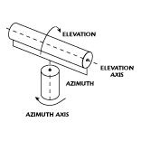
Azimuth-elevation Pedestals as shown in Fig.1
Fig.1 Azimuth-elevation Pedestals
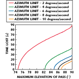
For azimuth elevation pedestal, the azimuth velocity of the pedestal is usually a limiting factor that prevents the LEO satellite from tracking the zenith, as shown in Fig. 2. For example, a base with a maximum azimuth speed of 4/sec will not be able to continuously track satellites with a 780 km solar synchronous orbit (UoSAT-3) for passage with a maximum altitude greater than 82 degrees. In the case of Zenith passing through, communication with the satellite will be lost for at least 45 seconds. This downtime is important when you consider that this type of satellite lasts only about 7.4 minutes at an altitude above 20 degrees during overhead passage.
Fig.2 shows the minimum time lost in seconds for passes of a satellite with a 780km orbit with different maximum elevations for an azimuth-elevation pedestal (which is azimuth limited) with maximum azimuth speeds of 2, 4, 6 and 8°/sec. The situation is even more critical when communication is via a single LEO satellite. In this case, it is not uncommon that during a significant period of time the only usable satellite pass may have a maximum elevation that requires azimuth movements in excess of the earth station’s pedestal capability. This condition occurs because all of the other available passes may have low peak elevation angles.
Azimuth-elevation-tilt Pedestals
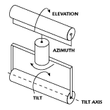
Fig.3 Azimuth-elevation-tilt Pedestals
An azimuth-elevation-tilt pedestal, shown in Fig.3 , is an azimuth-elevation pedestal with the addition of a third axis. The tilt axis is perpendicular to the elevation axis. This type of pedestal is also called a three-axis pedestal. At high elevations the elevation and tilt axes are used together to allow full hemispherical tracking of the satellite (including zenith passes); that is, the required elevation-pointing angle is obtained using a combination of the elevation and tilt axes. This capability reduces the elevation axis component of the required pointing angle and, thus, allows sufficient time for the azimuth axis to rotate without exceeding its maximum azimuth drive velocity.
However, the azimuth-elevation-tilt pedestal allows full hemispherical tracking it does have some disadvantages. The addition of the third axis increases the unit’s weight, complexity and manufacturing cost compared to either an X-Y or azimuth-elevation pedestal. Additionally, the interaction of the elevation and tilt axes adds the complexity of the required control electronics.
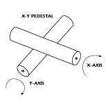
X-Y Pedestals
Fig.4 X-Y Pedestals
As shown above in Fig.4, an X-Y pedestal has two orthogonal axes: the first is a horizontal fixed primary axis; the second is perpendicular to and mounted on top of the first axis. This configuration allows the pedestal to provide zenith pass tracking even with the use of relatively low speed motors. An X-Y pedestal design offers several advantages over its azimuth-elevation-tilt and azimuth-elevation counterparts.
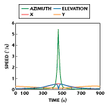
For an X-Y pedestal design the required angular velocities of both axes remain within a small range for all but the lowest elevation satellite passes. This condition is not the case for an azimuth-elevation pedestal where the required angular velocity in azimuth increases rapidly as the maximum elevation of a satellite pass approaches 90°. For an overhead pass of a LEO satellite with an 800 km orbit, the maximum angular velocity required by either axis is only a fraction of a degree per second. This low velocity produces improved pointing accuracy compared to the three-axis system where the angular velocity required is significantly higher. Another advantage is that the X and Y axes are identical, which means that the required spare parts can be kept to a minimum. In addition, the pedestal can be built from high quality, off-the-self components, which allow economical designs to be constructed for a wide range of operating conditions and antenna sizes. Off-the-self components also mean low cost maintenance. The X-Y pedestal uses brushless DC motors, which eliminate the need for expensive rotary joints and slip rings. Finally, the X-Y pedestal is a low cost solution where the simplicity of the design compared to a three-axis pedestal increases the mean time between failures.
A standard PC can be used to control the X-Y pedestal, allowing software adjustment of parameters such as tracking speed and tracking range to be set by the user. Two resolvers (one mounted on the shaft of each of the two motors) provide feedback on the antenna pointing angles. Note that an X-Y pedestal is still not capable of full hemispherical tracking but, unlike the azimuth-elevation pedestal that is unable to continuously track high elevation passes, the X-Y pedestal has its limitations at low elevation angles (<2°) around 90° and 270° in azimuth. At these elevations the satellite moves slowly with respect to the earth station and even small capacity motors (6°/sec) are sufficient to minimize the tracking loss. In any event, it is difficult to imagine a practical application in which such low elevation passes would be required.
For more info, please email sales@antesky.com.

