Three Common Antenna Installation Modes

According to many years of experience engaging in antenna and related accessories, users who purchase motorized antennas generally have many problems with the wiring of the antenna and the antenna controller, so we are here to talk about the wiring of the motorized antenna and its controller.
- we introduce the wiring point of all motorized antennas
The following components will be added for motorized antenna compared with manual one.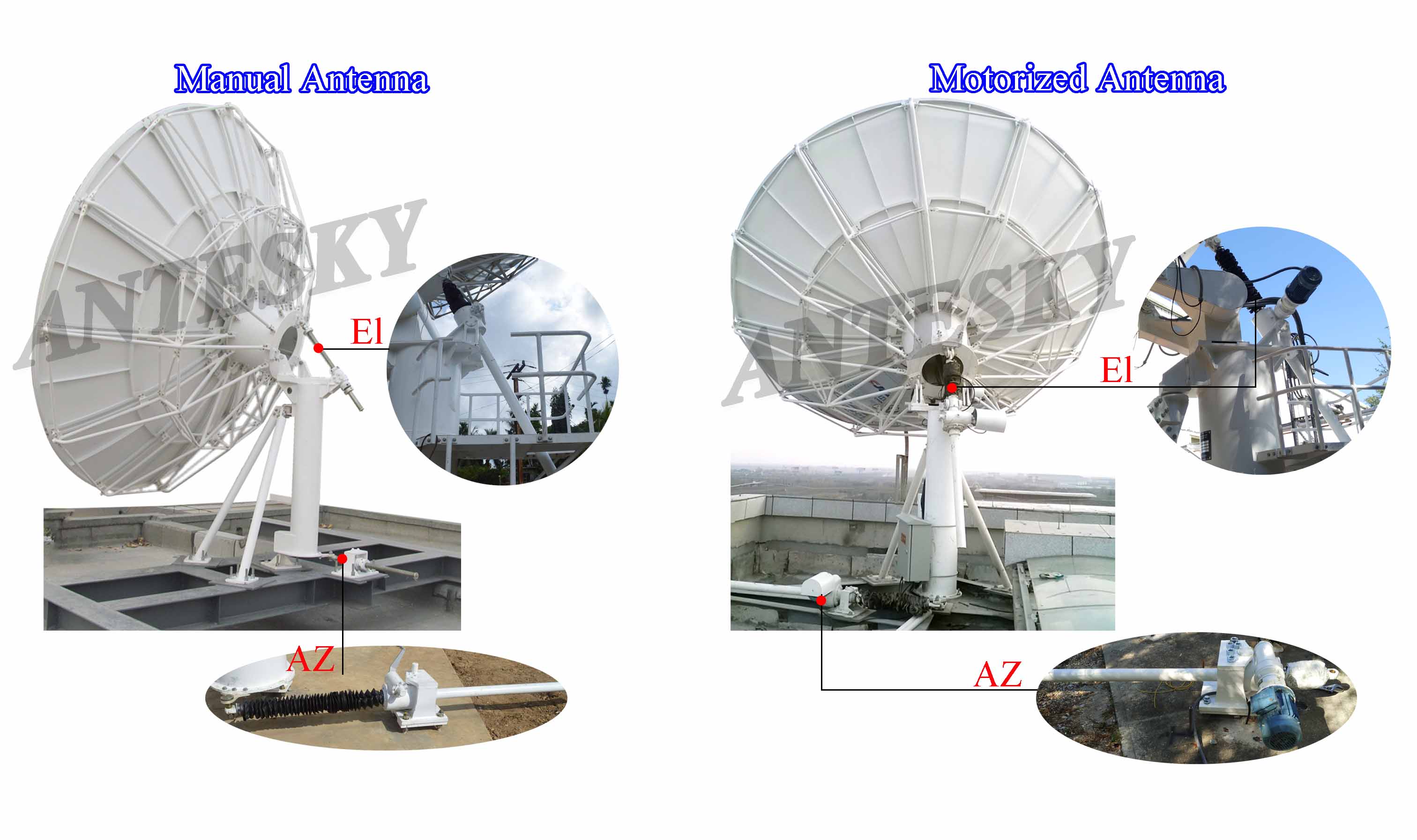
- Motor reducer combination
A motor reducer combination will replace the manual screw device including AZ, EL and polarization screw mechanism;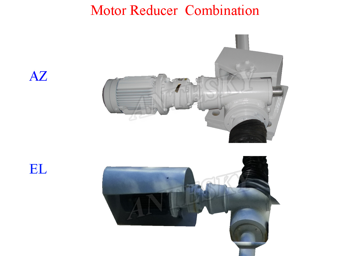
- Limit switch
In order to prevent the antenna from turning out of the range that it can rotate, we add limit switches to the azimuth, elevation, and polarization, making antenna rotate in a certain range. Normally, Restricted antenna-the azimuth rotation range becomes +-60°; the pitch is 5-90°; the polarization is +-90°.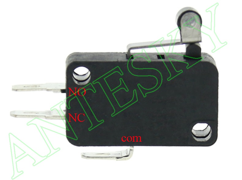
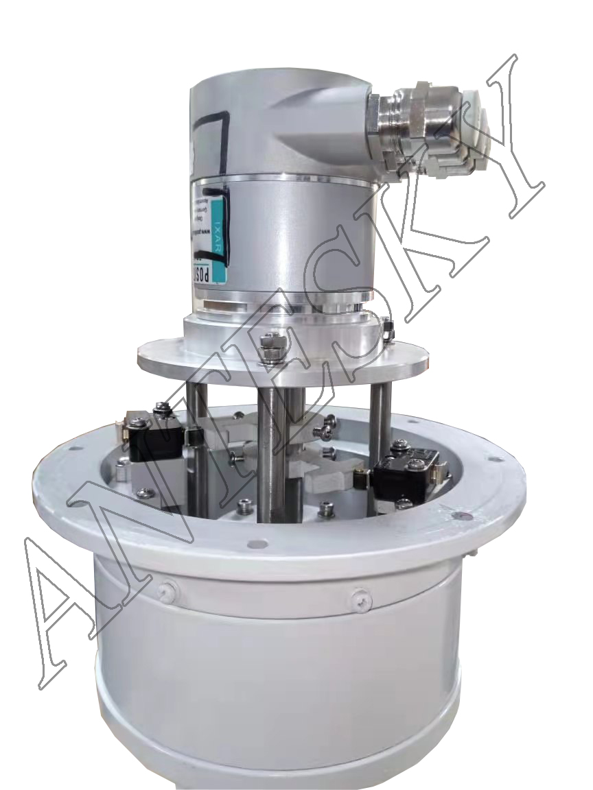
- Angle encoder
Angle encoder is for an option for motorized antenna controller system. If you need to display the angle of the antenna rotation on the controller, you need to add an angle encoder to display the angle for a long time.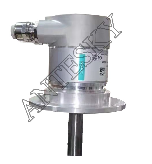
From the above additional components, we can know that there are the following three points in the connection between the motorized antenna and the controller:
- Motor wiring
- Limit switch wiring
- Encoder wiring
2. let us introduce the corresponding interface betweenthe controller and the motorized Here we will take our company’s simplest controller ATSK805 as an example.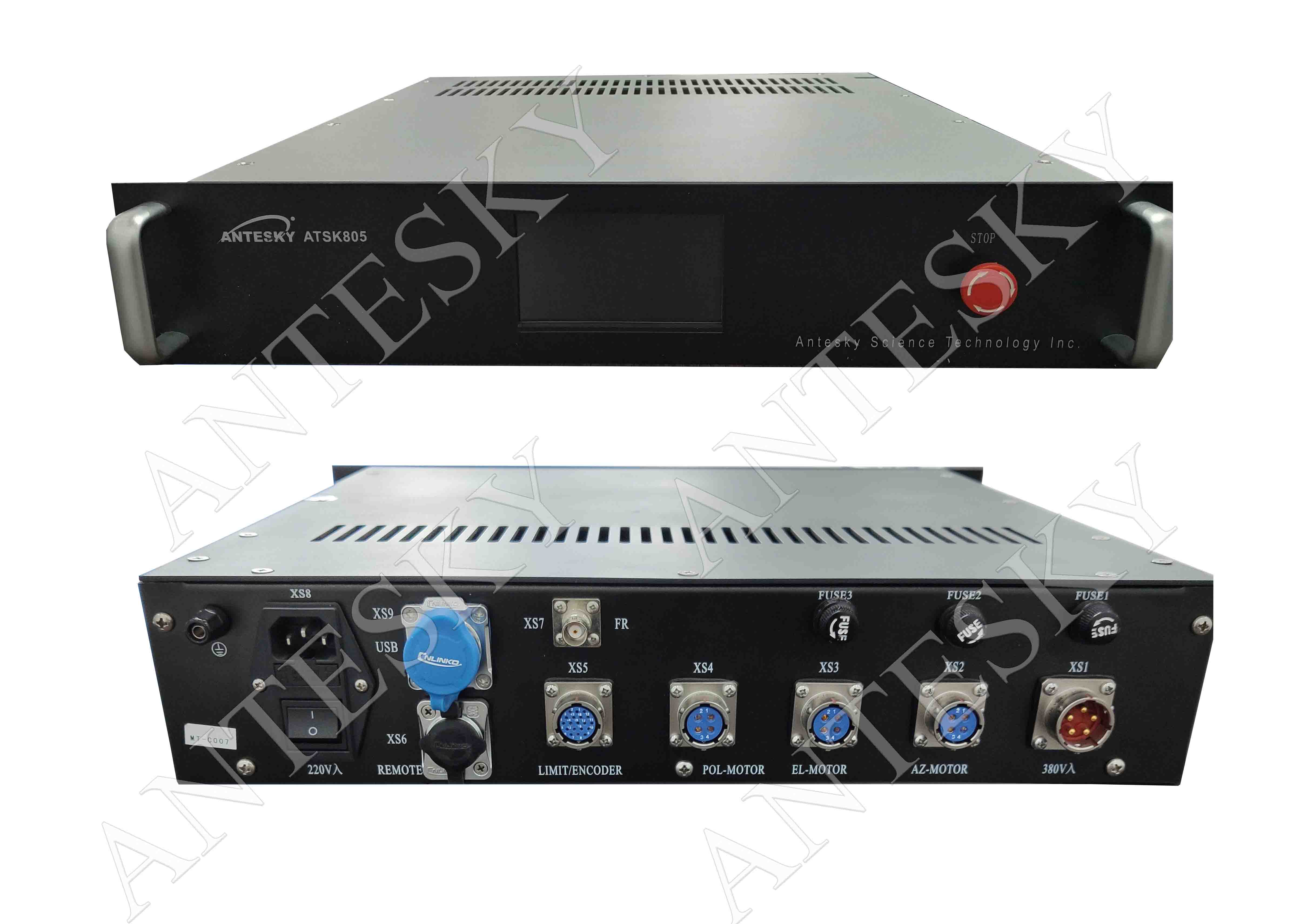
3, regarding the wiring of these three places, take our ATSK805 wiring system as an example to show the wiring of the entire system. 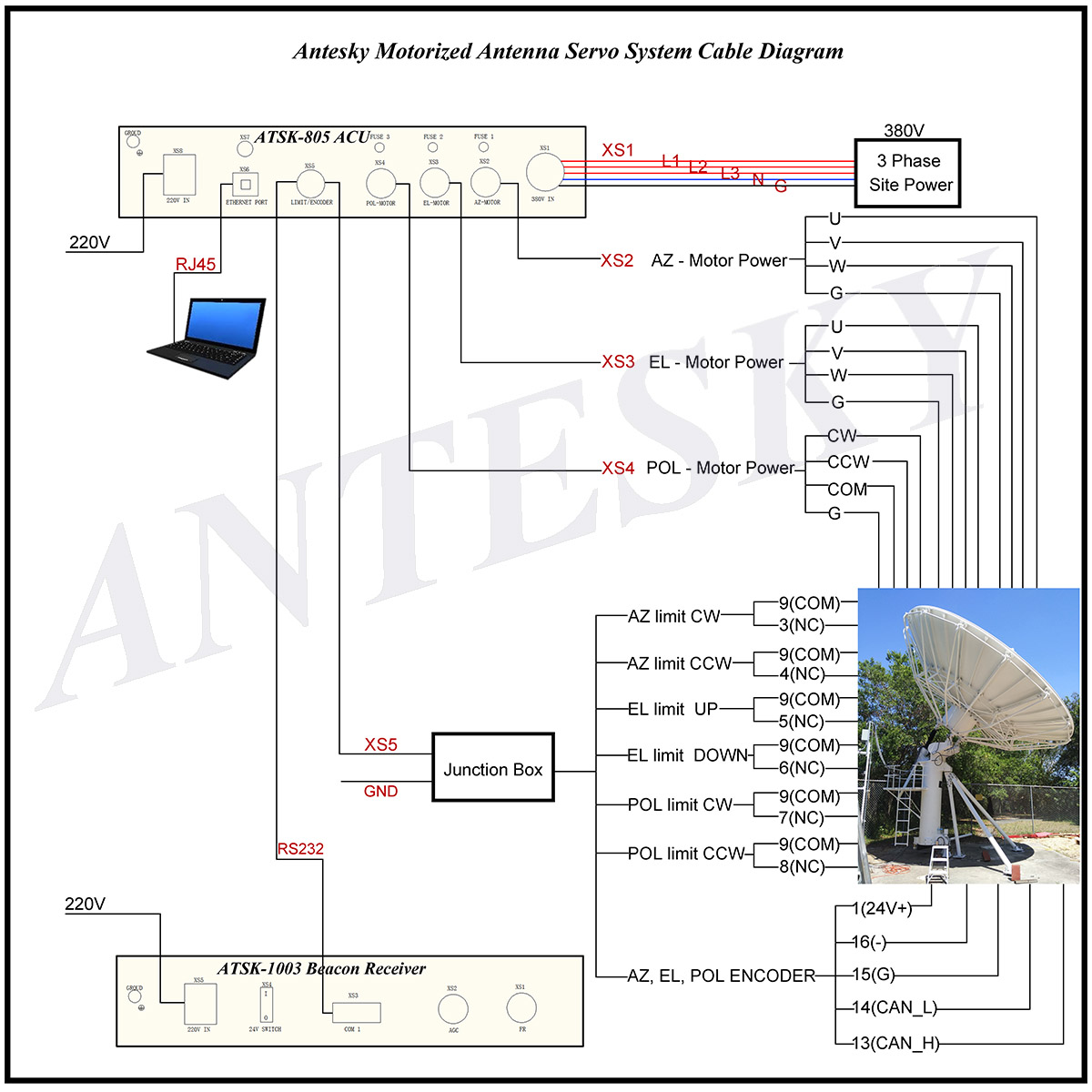
Diagram of cable list for ATSK805 Controller system for reference.
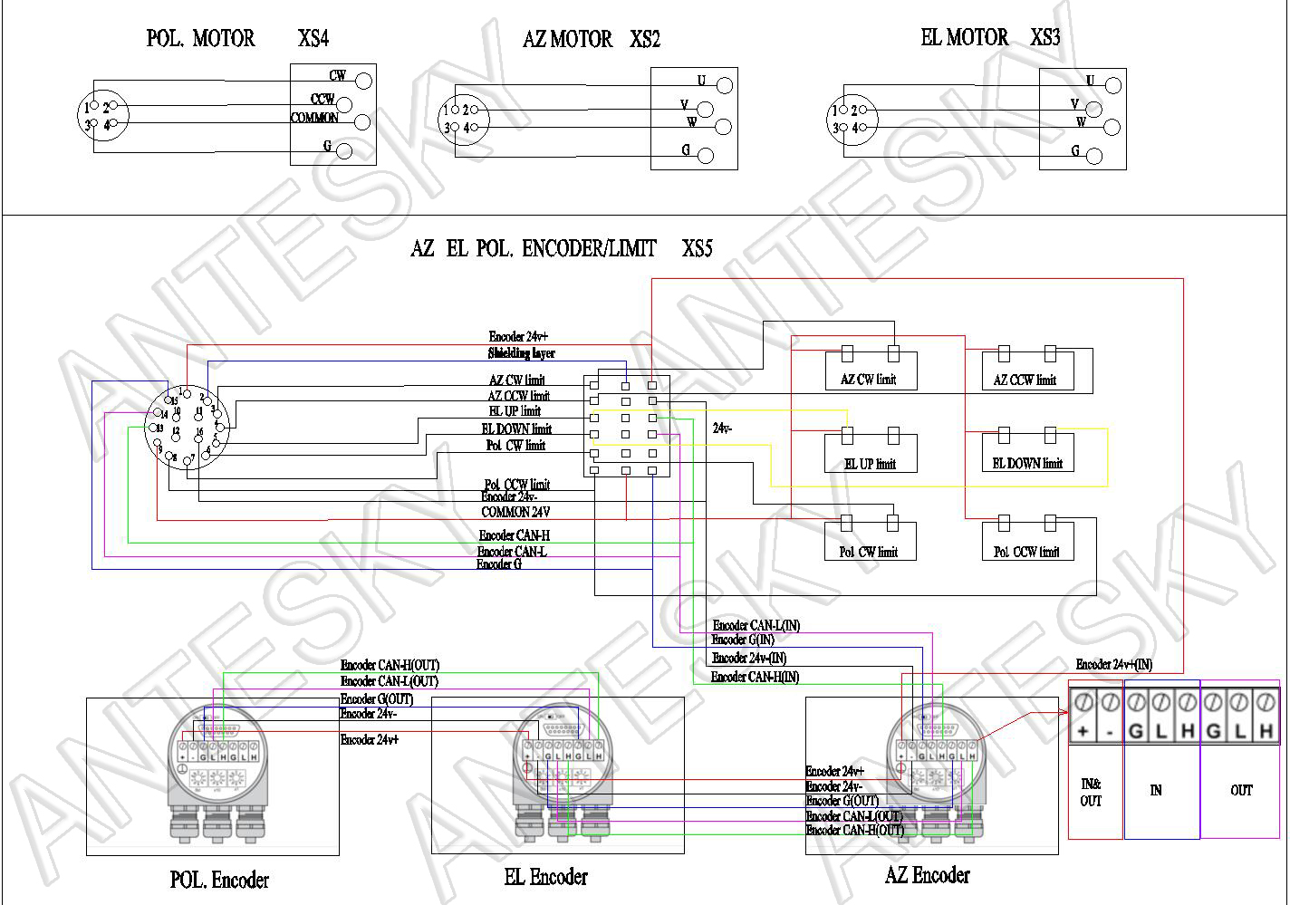
Table of cable list for ATSK805 Controller system for reference.
ACU
| Cable | Function | Remark |
| Power cable | Power supply of AZ/EL/POL. | |
| Control cable(Junction box included) | Limit and encode | |
| Ethernet cable | Ethernet | Provided by client |
| ACU power cable | ACU power supply | |
| Motor power cable | 380V motor power supply |
Beacon receiver
| Cable | Function | Remark |
| Power cable | Beacon receiver to power | 3-cores |
| RF cable | Beacon receiver to LNA |
Antenna connection
| Aviation plug | No. | Terminal No. | Remark |
| AZ&EL | 1 | U | AZ&EL MOTOR |
| 2 | V | ||
| 3 | W | ||
| 4 | G | ||
| POL. | 1 | CW | POL. MOTOR |
| 2 | CCW | ||
| 3 | COMMON | ||
| 4 | G | ||
| Control cable (Limit&encoder) | 1 | 24V+ | ENCODER |
4. Cautions during operation
4.1 Check &Identify cables
After the goods arrived, the user needs to check all the cables and related wiring. Before leaving the factory, the cables will generally have a mark (wire mark), but due to transportation problems or disassembly of the package, the wire mark may fall, which makes the user unable to distinguish cables, then how to distinguish cables at this time?
1) First, we need to check the system wiring diagram provided by the supplier (as shown above), and check the wiring according to the system wiring diagram one by one.
2) If there are more cables and confusion, then we need to use multimeter to distinguish (please refer to the following method of using multimeter.)
Multimeter using instructions to measure cable connection situation as follows.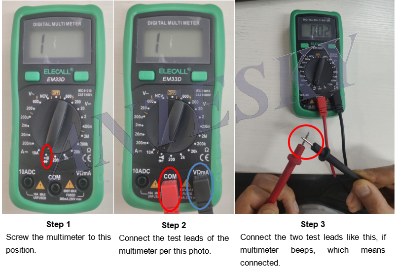
Remarks: After completing the above 3 steps, please connect a wire to both sides of the multimeter pen. If the multimeter beeps, which means it has been adjusted. Then find the corresponding wire cable according to the aviation plug mark of 1/2/3/4…etc.
3) Here again, if the cables are a messy, you must check the system diagram several times and check the related wiring definitions as well by using a multimeter to distinguish each cable. After distinguishing each cable, perform wiring and welding.
4) If there is still a problem after confirming the cable several times, you must contact the supplier to confirm that there is no problem with the cable before you can connect and weld the wire for a test run; please be sure to confirm that it is correct and then perform a test run. Because improper wiring may cause loss of related parts after power-on.
5. The following is a case study and related introduction about Antesky ATSK805 ACU.
In 2013, one of African clients ordered 2 units of Antesky controller system and sent email to us saying it was awesome doing business with us and when he got the goods, he sold it to Congo client, and the final customer use it well without any question. After been for years, no doubt that Antesky controller had been optimized and upgraded continuously as per client feedback. Today, let us show this model of Antesky ATSK805 ACU, which is widely used in the market because of much easier operation and more cost-effective price. Here we are mainly attached more importance for the operation and maintenance of cable wiring between antenna controller system and motorized antenna.
This type of Antesky antenna controller with the model of ATSK-805, as a suit of antenna pointing system, it can manually or automatically control antenna to rotate precisely pointing to the satellite. The ACU adopts ARM9 series microprocessor and thus reliably guarantees the accuracy and stability for antenna tracking system. Provided with standard RJ45 cable interface, the system can realize remote control. This ACU is designed by a 4.3-inch color touch screen with decent appearance and easy for operation as well. Normally, this ACU adopts 3 axis including Az, El and Pol. control, Antenna Control and drive unit are integrated in a 2U cabinet. We can also provide 4 or 5 axe s control in according to user’s requirement too. It is a reasonable solution for medium or small earth station antenna.
We are welcome you to contact with Antesky for any question or help during cable wiring or operation of controller via sales@antesky.com or WhatsApp us directly. Thanks in advance.
6. Learn more about ATSK-805 Antenna Controller
Antenna controller feedback from South Africa
Related posts


