1. Overview of 2.4M Ka band Auto-Pointing Flyaway Antenna System
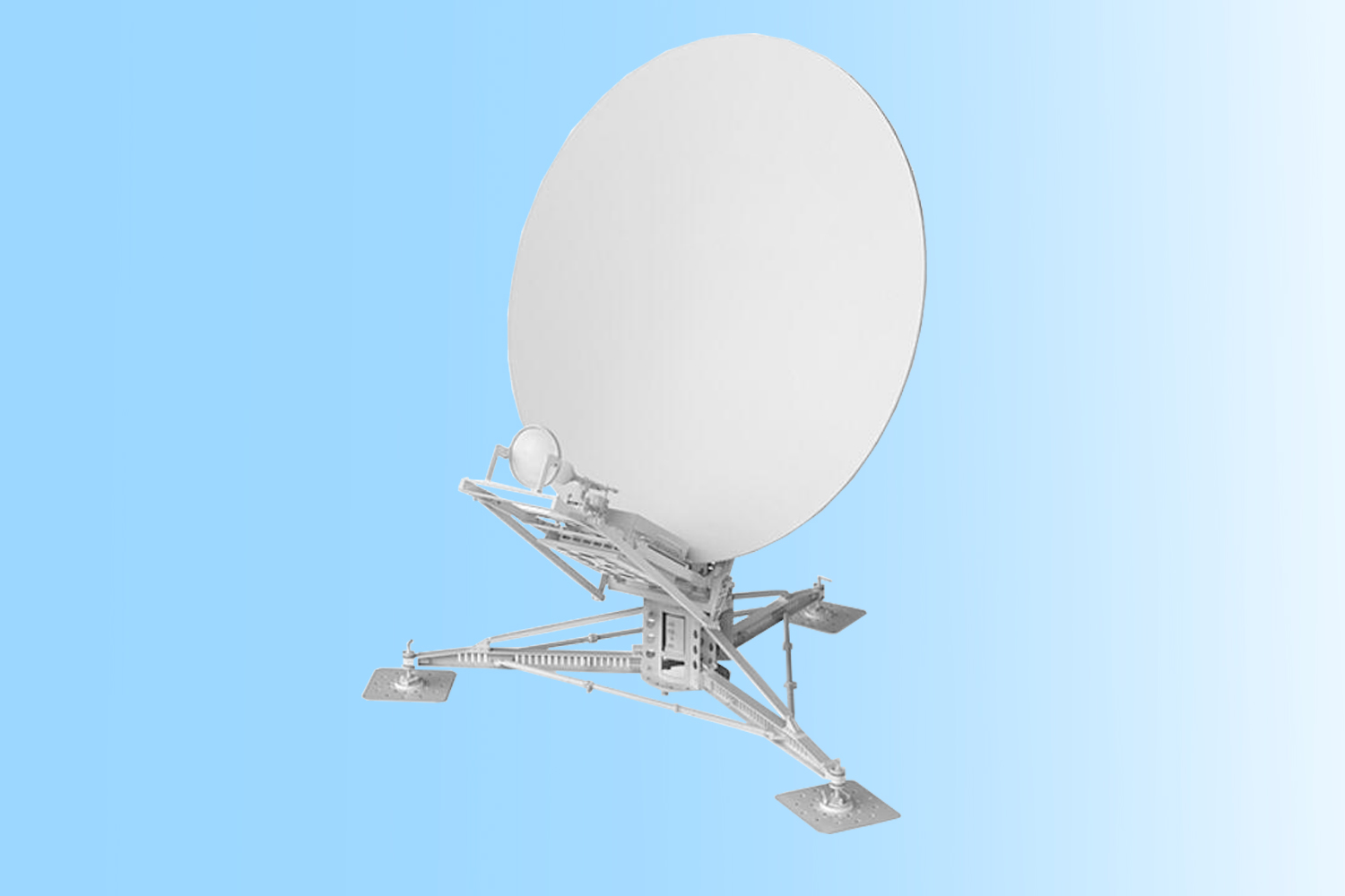
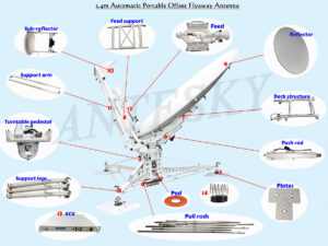
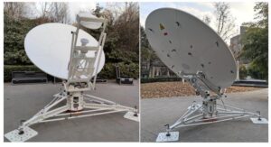
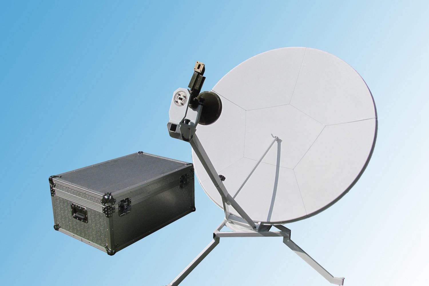
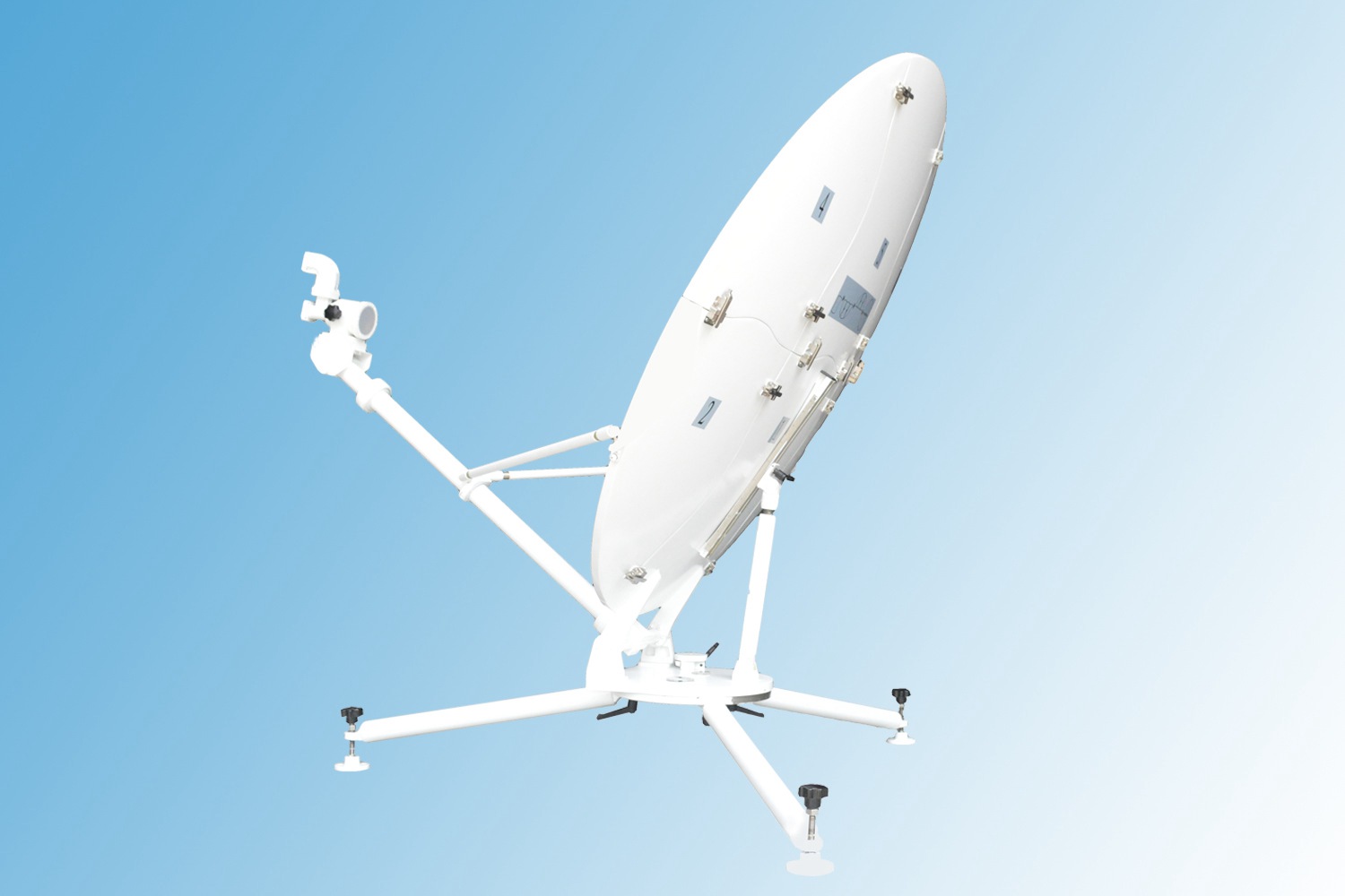
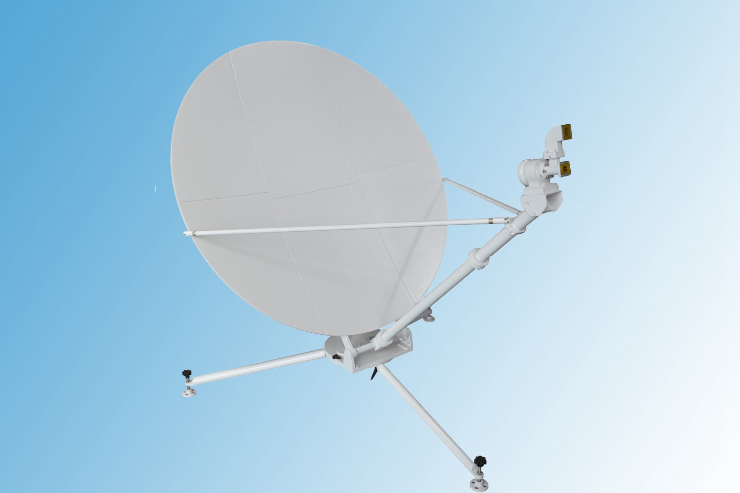
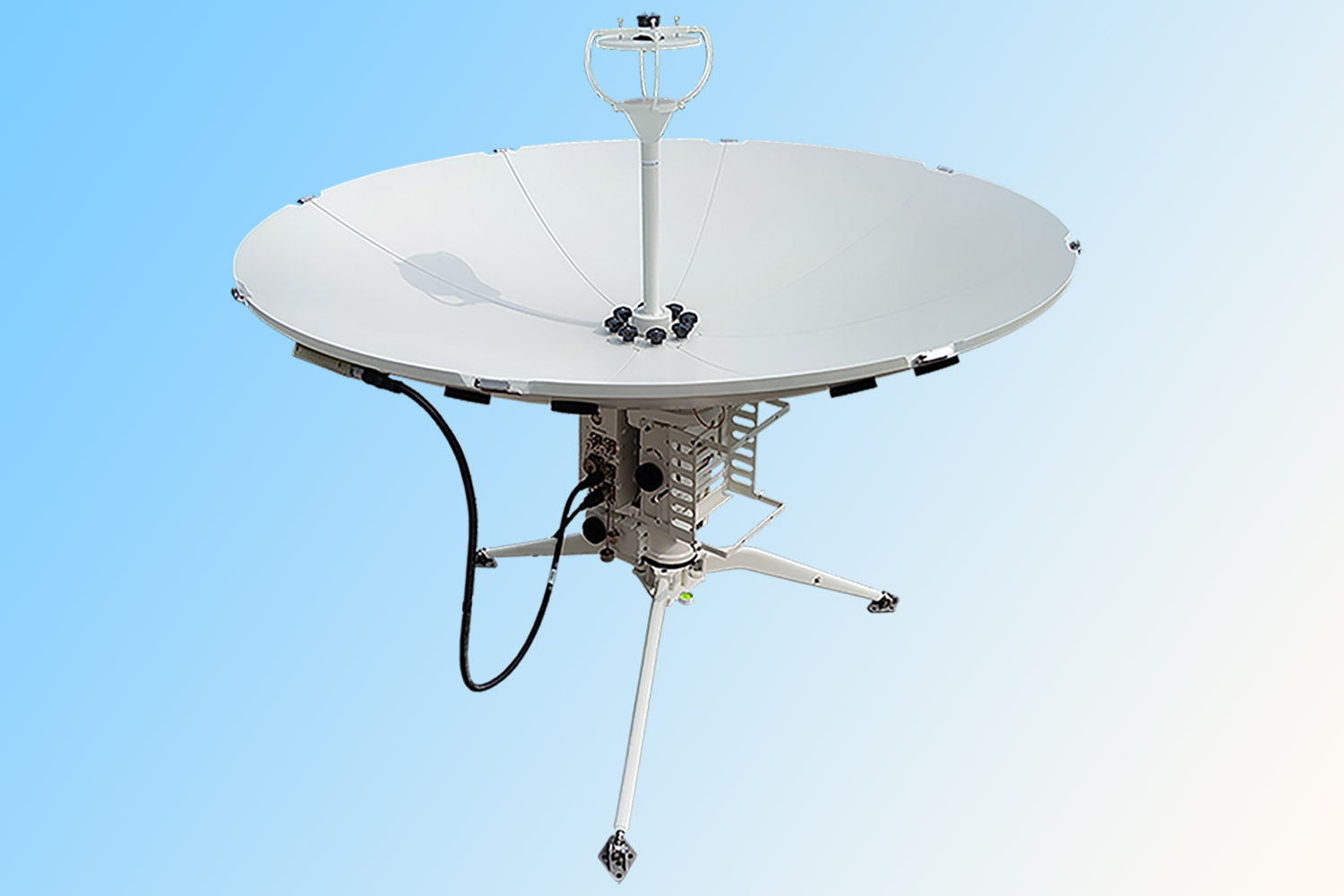
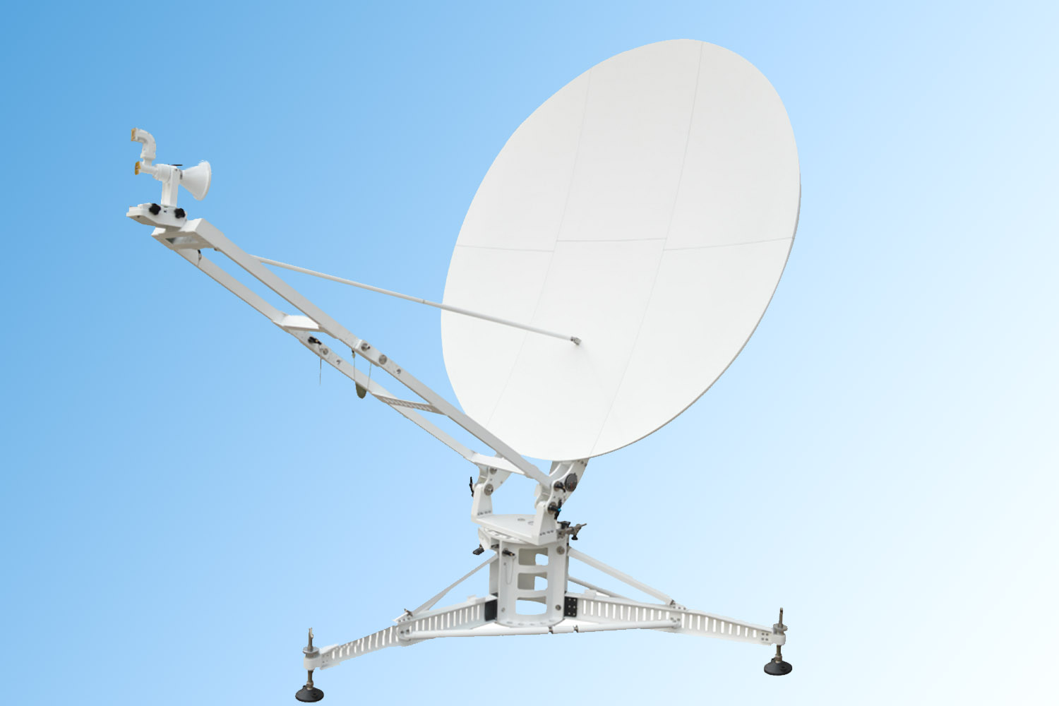
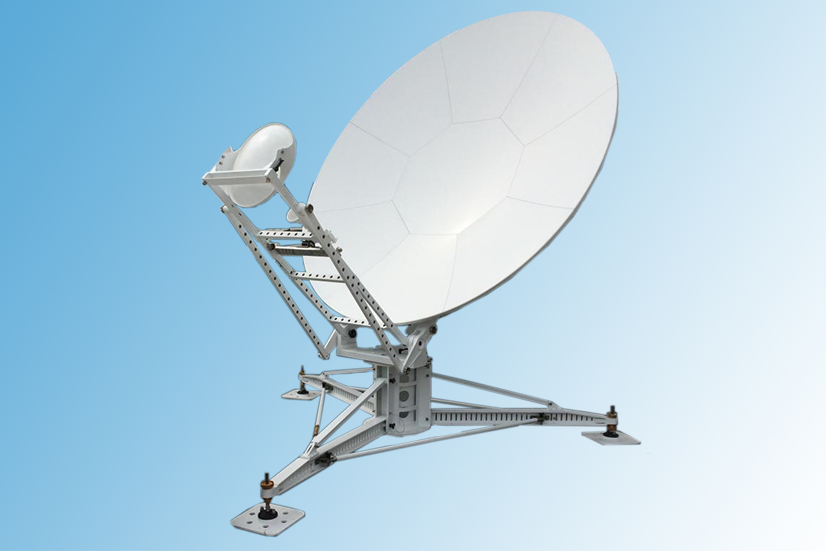
ACF-240KA 2.4m auto-pointing moveable flyaway antenna system from Antesky, with Gregorian dual-reflector offset feed, is mainly composed of turntable pedestal, support legs, back structure, support arm and motorized push rod etc. Antenna control subsystem includes azimuth, elevation, polarization motor and ACU chassis. Antenna tracking subsystem contains beacon receiver, angle sensor, GPS, WiFi module, ATPC control board.
ACF-240KA Antenna panel is made of composite carbon fiber material with light weight and high surface accuracy of 0.3 RMS. The Gregory double offset reflector design is updated with excellent electrical performance of low side lobe and remarkable cross-polarization. This flyaway antenna features 8 petals of carbon fiber panels, which can be assembled repeatedly with high precision.Two persons can assemble and no tools required during installation.
ACF-240KA 2.4m auto-pointing moveable flyaway antenna is suitable for for temporary or frequently changing installation sites, or in where no regular communication means on the ground including earthquake disaster relief, TV broadcasting, maritime affairs, exploration, meteorology and other emergency communication fields. It can meet the requirements of CCIR 580-6, ASIASAT and INTELSAT as well.
2. Key Features of 2.4M Ka band Auto-Pointing Flyaway Antenna System
- Meet the requirements of CCIR 580-6, ASIASAT and INTELSAT;
- Panel using the latest carbon fiber composite materialfor light weight;
- Gregoriandual -reflector offset feed design with low side lobe and remarkable cross-polarization
- Antenna system is equipped with GPS positioning system, position detection system, polarization adjustment system, servo drive system, automatic protection system, high-performance satellite beacon receiving system, antenna controller.
- Motorizedand manual control modes available to facilitate emergency operation in various environments.
- Customized aviation package material optional.
3. Technical specification of 2.4M Ka band Auto-Pointing Flyaway Antenna System
| Product name | 2.4m Ka Band Auto-Pointing Moveable Antenna | Feed type | Dual-reflector, offset | ||||
| Model | ACF-240KA | Diameter | 2.4m | Polarization | Circular | ||
| Antenna frequency | Rx.: 17.7~21.2GHz | Antenna gain | Rx.: ≥50.8+20lg(f/19.45) dBi | ||||
| Tx.: 27.5-31.0 GHz | Tx.: ≥54.3+20lg(f/29.25) dBi | ||||||
| Port isolation | Rx. To Tx.: ≥ 85 dB (LNA input) | VSWR | Rx.: ≤ 1.3 | ||||
| Tx. To Rx.≥ 40 dB (BUC input) | Tx.: ≤ 1.3 | ||||||
| Axis ratio | ≥ 2.0dB(On axis) | First sidelobe | ≤ -14 dBi | ||||
| Feed interface | RF interface: WR42, WR28 | Port | 2 ports | ||||
| MF interface: N-50K | Controller | Standard 19 inch 1U chassis | |||||
| Rotate range | AZ | ± 200 ° | Rotate speed | AZ | 0.1°~3 °/s | ||
| EL | 10°~85° | EL | 0.1°~1 °/s | ||||
| G/T value | ≥24.3 dB/k | ||||||
| Aligning accuracy | ≤ 0.3dB (R.M.S) | Position mode | Automatic position, manual as option | ||||
| Temperature | -30°C~+60 °C | Operation wind | ≤11m/s (Ballasting) | ||||
| Storage temperature | -40°C~+70 °C | Survival wind | ≤18m/s (Ballasting) | ||||
| Humidity | ≤95% (20℃) | Protection level | IP65 | ||||
| Power supply | 100~240 VAC,50Hz~60 Hz | System power consumption | ≤ 100 W(Not included BUC, No wind) | ||||
|
OPTIONS |
|||||||
| Finishes Color
Green, tan or per customer demand |
Frequency available
Ka-band,Ku band,C band |
Drive mode
Manual or motorized |
|||||
5. Assemble guidance of 2.4M Auto-Pointing Flyaway Antenna System
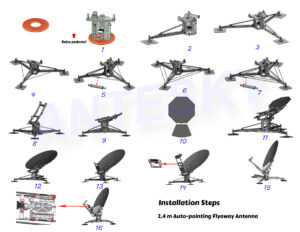
Find a level ground site (flyaway antenna with no requirements for the foundation). Firstly, check the components according to the provided packing list. If there found no any lost or damage, then take out the components respectively to start assembling.
For installation details , please click for installation video of 2.4m auto-pointing flyaway antenna.
6. Package & shipping dimension of 2.4M Auto-Pointing Flyaway Antenna System
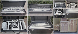
- In 8 carbon fiber aviation cases
Box Description DIM(L×W×H)MM G.W(KG) N.W.(KG) 1 Support arm box 1320*860*750 0.85CBM
90 55 2 Back structure box 1760*1060*510 0.95CBM
81 45 3 Panel box A 1220*660*1150 0.93CBM
54 38 4 Panel box B 1110*780*1290 1.12CBM
75 49 5 Support legs box A 1620*630*570 0.58CBM
85 40 6 Support legs box B 1910*520*580 0.58CBM
79 43 7 Turntable pedestal box 890*760*960 0.65CBM
81 30 8 Feed box 1200*810*690 0.67CBM
36 24 Total 6.33CBM 581 324
8. Learn more about 2.4M Auto-Pointing Flyaway Antenna System

