1. Overview of ATSK-805 Antenna Controller
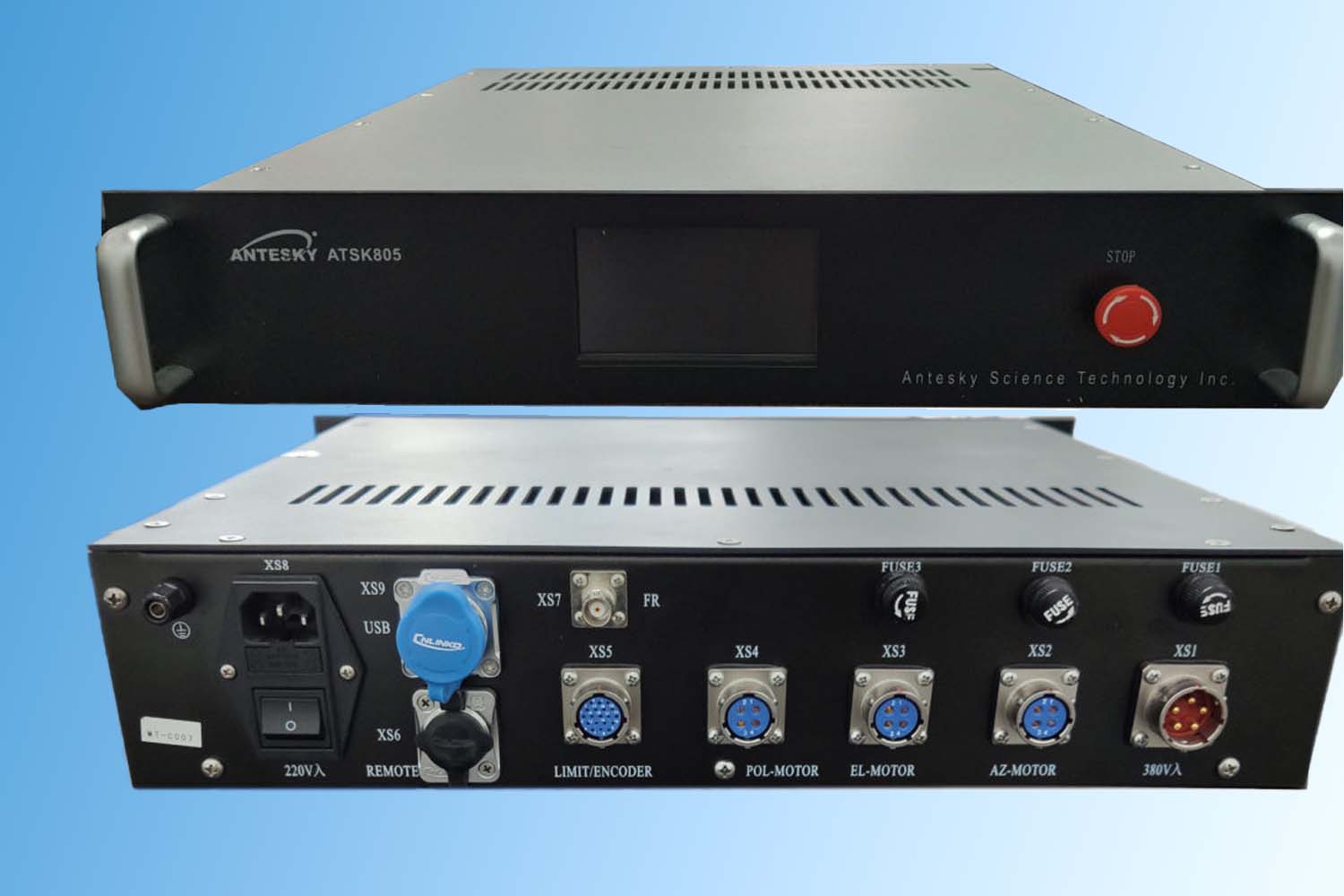
This ATSK-805 Antenna Controller, as a suit of antenna pointing system, it can manually or automatically control antenna rotation to precisely pointing to the satellite. The ACU adopts ARM9 series microprocessor and thus reliably guarantees the accuracy and stability for antenna tracking system. Provided with standard RJ45 cable interface, the system can realize remote control. The human-computer interface is designed by a 4.3-inch color touch screen with decent appearance and easy for operation.
The standard product configuration provides 3 axis, Az, El and Pol control, we can also provide 4 or 5 axe s control in according to user’s requirement. Control unit and drive unit are integrated into one 2U standard chassis with multi-speed inverter.
2. Key Features of ATSK-805 Antenna Controller
- Can manually or automatically control antenna;
- Adopts ARM9 series microprocessor;
- Provided with standard RJ45 cable interfaceto realize remote control;
- Easy for operation with 3-inch color touch screen;
- Control unit and drive unit are integrated into one 2U standard chassis with multi-speed inverter.
3. Technical specification of ATSK-805 Antenna Controller
| Product | ATSK-805 Antenna Controller |
| Tracking precision | Antenna pointing accuracy within ten percent of 3dB beam width |
| Position sensor | Single lap 13-bit photoelectric sensor, precision±0.04° |
| Absolute single-ring 16-bit photoelectric sensor for option | |
| Display resolution | 0.04° for both Az and El axes (standard 13 bits)
0.01° for both Az and El axes (optional 16 bits) 0.1° for polarization |
| Number of present satellites | Preset up to 100 satellites |
| Power input | 220 (1±10%) V, 50 (1±5%) Hz; power consumption: 300VA
380 (1±10%) V, 50 (1±5%) Hz; power consumption: 3KVA |
| Tracking interface | (0-10V) analog voltage input interface, BNC connector |
| Remote communication interface | RJ-45 Ethernet interface |
| System wiring | Motor cable RVVP4*1.5mm²
sensor and Limit switch cable RVSP2*6*0.5mm² |
| Safety | Software and hardware travel limits switches offer guarantee for the rotation of antenna |
4.System configuration of ATSK-805 Antenna Controller
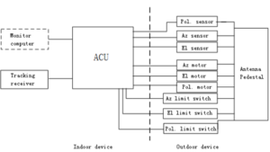
Below is the whole block diagram of antenna servo system. The indoor equipment includes ACU, track receiver and computer; the outdoor equipment include antenna, drive motor, sensor and limit switch.
The ACU can communicate with computer, receive monitoring commands & data and report servo status via standard RJ-45 cable connection. Other interfaces of the ACU include those with track receiver, antenna motor, limit switch and sensors.
Now please click this guidance for referring to how to do cable wiring between controller system and antenna itself.
5. Package & shipping dimension of ATSK-805 Antenna Controller
- Packing list
| Item | DESCRIPTION | QYT(Case) | SIZE(L×W×H)mm | G.W(KG) | N.W(KG) |
| Antenna Controller | Antenna Controller | 1 | 640*540*320
0.11CBM |
20 | 17 |
| Antenna Controller Cables | 1 | 640*540*320
0.11CBM |
39 | 36 | |
| Total | 2 | 0.22CBM | 59 | 53 | |
- Package details
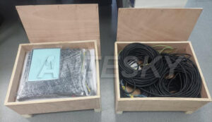
-Packed in 2 customized rigid plywood cases
6. Project case and customer feedback of ATSK-805 Antenna Controller
7. Learn more about ATSK-805 Antenna Controller

