Typically, radio frequency devices(RF devices)include two types of active devices and passive devices. Active components are microwave components that require external power supply, such as PA, LNA and RFIC, etc. Passive components include passive filters, power dividers, and other microwave components that can work without external power supply. Whether it is an active device or a passive device, it is a necessary part of the radio frequency circuit. Today we will first learn about the four most common passive devices – isolators and circulators, couplers and power dividers. Please see the analysis below.
1. RF isolator(RF devices)
Q: What is an RF isolator(RF devices)?
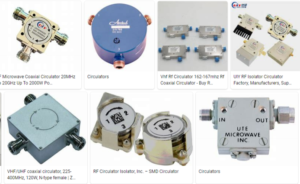
An RF isolator is a two-port device that prevents RF energy from returning to its source. It is similar to a diode that only allows current to flow in one direction, or a check valve in a fluid flow system. Note that an RF isolator has absolutely nothing to do with galvanic (ohmic) isolation used in non-RF signal and power designs, and it is not galvanic isolated. Common isolators on the market are as follows.
Fig.1 Common isolators(RF devices)
Q: Why need an isolator(RF devices)?
It is mainly used to protect other RF components from excessive signal reflections. For example, isolators are used in test applications to provide electrical isolation between a device under test (DUT) and sensitive signal sources. This is done with some of the energy at the DUT being reflected back to the source.
2.Circulator(RF devices)
Q: What is a circulator(RF devices)?
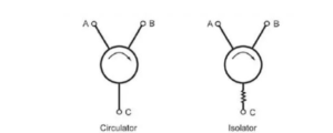
A circulator is a three-port device used to control the direction of signal flow (radio frequency energy) in a circuit. Note that the isolator is also a circulator with a third port terminated with a matched load. The circulator is shown in the figure 2 below.
Fig.2 circulator(RF devices)
Q: Where are circulators used?
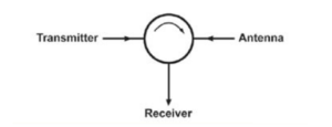
The most common application for a circulator is when the transmitter and receiver share a single antenna, ensuring that high power transmission signals do not reach the sensitive receiver input ports where they could be overloaded and possibly damaged. (The general term for this function is a duplexer.) Ideally, the transmitted signal energy output will only reach the antenna port without being “seen” by the receiver, and the received signal will only go to the receiver. (Note that there are other ways to achieve duplexer functionality, including using more expensive cavity duplexers.)
Q: What are the key performance parameters and their typical values?
These are the ones most commonly associated with RF devices and functions (as passive devices they of course don’t provide any gain):
Isolation: Typically 10 dB to 25 dB, depending on the match between the isolator/circulator and the load.
Insertion Loss: As long as there is a device between the source and the load, there will be some loss. The insertion loss of these devices is typically less than 1 dB.
Power Capacity: Unavoidable losses in ferrites cause heat to have to be dissipated at excessively high temperatures, which can reduce or damage the effectiveness of the ferrite material. The power capacity refers to the maximum power that the circulator/isolator can carry, exceeding its power capacity, the circulator/isolator may be damaged.
Bandwidth/frequency range: refers to the operating frequency and operating bandwidth of circulators and isolators. Through optimized design, standard isolators and circulators can reach tens of GHz.
3.Coupler(RF devices)
Q: What is a directional coupler(RF devices)?
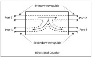
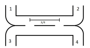
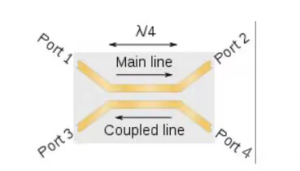
It is a four-port device, where Port 1 is the entrance port, and Port 2 is the through port (because it is connected by a straight line). Port 3 is a coupled port and port 4 is an isolated port. Likewise, if a signal is incident on port 2, port 1 is therefore a thru port, port 4 is a coupled port, and port 3 is an isolated port. The diagram of coupler is as shown below figure 3.
Fig.3 Directional coupler
Q: What are the main parameters of a directional coupler of RF devices?
First, as with most microwave devices, S-parameters are required to fully characterize performance. Basic specifications are similar to other microwave components. Assuming port 1 is the incident port, there is insertion loss (IL) between port 1 and port 2; isolation between port 1 and port 4 (I – ratio of incident power to back reflected power); port 1 and port Coupling between 3 (C – ratio of incident power to forward power); directivity between ports 3 and 4 (D – ratio of forward power to reverse power); all in dB.
Q: How are directional couplers of RF devicesactually built?
There are two common ways: using waveguides or using transmission lines (with many sub-variants). Basic waveguide couplers use precisely spaced and sized holes that are a function of wavelength and bandwidth (and the holes may have non-circular shapes) to allow power to flow between two physically aligned waveguides. Therefore, the energy incident on port 1 mixes with the energy incident on port 3.
Q: What about coupled line couplers of RF devices?
Clearly, many applications cannot use waveguides due to their size, cost, and other concerns. In some cases, another option is an RF transmission line based coupler. It uses a pair of dimensionally precise unshielded transmission lines carefully aligned with each other. These lines can be discrete transmission lines or even stripline/microstrip implementations.
4. Power splitter (RF devices)
Q: What is a power splitter of RF devices?
As a complement to the coupler, the power splitter has many similarities. A splitter (also known as a power splitter) absorbs some of the incident energy and diverts it to another port. The ratio of “separation” can be half of each port, or a fraction of what is needed to sample the incoming signal for test and measurement purposes. (eg between 1% and 10%)
Q: How is the power distributed?
As with couplers, there are many ways to do this. A widely used method is the Wilkinson power divider, which uses split transition lines built from physical lines or stripline/microstrip lines.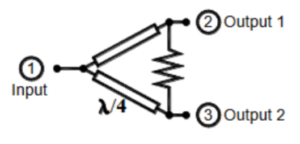
The above is brief introduction about common passive devices including isolators, circulators, couplers and power dividers. We hope you can learn more from this article. In the next article, we will introduce RF active devices in satellite communication systems, please continue to pay attention to our website update. For any questions and assistance, please contact Antesky via sales@antesky.com.

