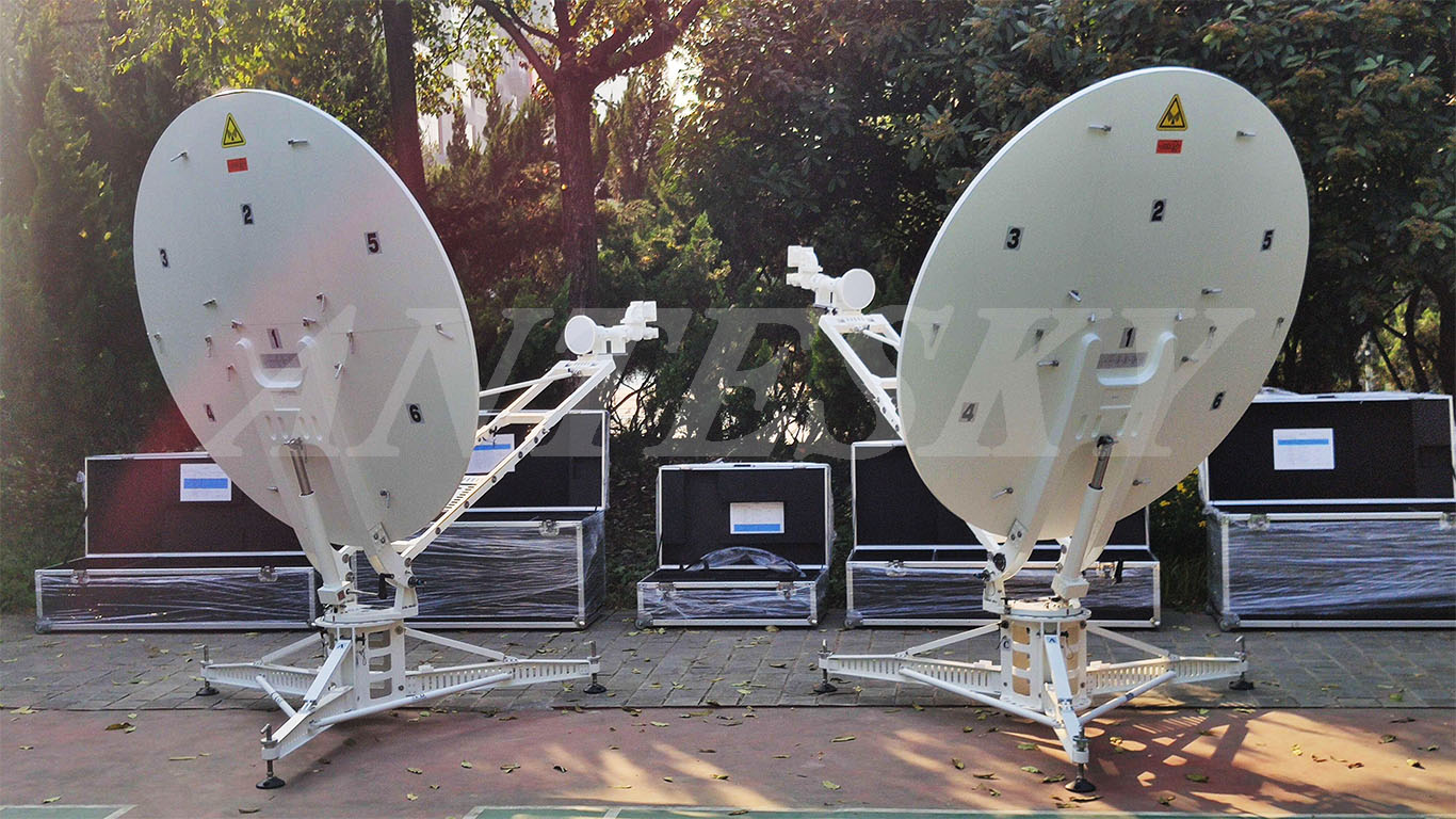
Client ordered 3 sets of 1.8m flyaway satellite antennas with C band this October. Compared with other previous cases, this time client required us to offer a solution about waveguide quick connectors between the flexible waveguide and the straight waveguide both ends.
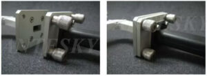
Regarding the quick connectors for the waveguide flange, please view the Ku band WR-75 quick connectors below for reference.It easily connects two flanges without tools or having to tighten all the flange screws every time.
Ku band WR-75 quick connectors
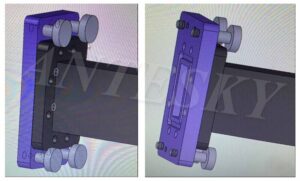
For C-Band flange WR137G, because it has more screws.There needs to be a cover for opening the flange when disconnecting them.
C-Band WR137G quick connectors
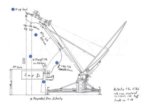
Below are required waveguides lists of 1.8m manual flyaway satellite antenna that we provide as per client.
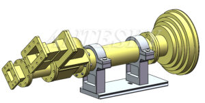
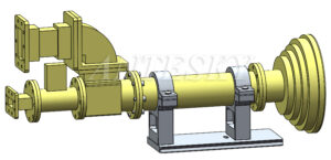
The diagram of 1.8m flyaway satellite antenna waveguide position
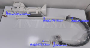
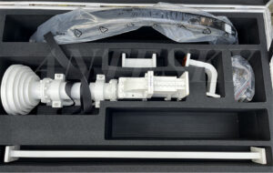
Waveguides photos of 1.8m flyaway satellite antenna
Table 1 waveguides lists of 1.8m manual flyaway satellite antenna
| No. | Components | Quantity | Specification | Remark |
| 1 | Rectangular curved waveguide TX | 1pc | 100mm*100mm | Tx port of feed horn |
| 2 | Straight waveguide | 1pc | 800mm | |
| 3 | Straight waveguide | 1pc | 100mm | |
| 4 | Quick connectors | 1pc | ||
| 5 | Flexible waveguide | 1pc | 1100mm |
Waveguides package of 1.8m flyaway satellite antenna
We believe these physical waveguide photos are clear to identify for customers during installation. Also, as you can see that these components are packed with feed together in one carton, customer does not need to add another package, which will help them to save the extra cost.
Apart from some quick release waveguides, client is care about operation of LHCP & RHCP Switching.
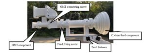
While how to switch between LHCP and RHCP? the operation steps are as follows:
- Loosen the OMT connecting 8 screws;
C band feed introduction of 1.8m flyaway satellite antenna
- Rotating the OMT component by 2 screw holes ( rotate 90°), fix it with OMT connecting screws. (Whether you rotate CW or CCW, either is OK.) as shown in the figure below:
- Loosen the feed fixing screw, then rotate the C-band feed component 90° to ensure that the side of the OMT component is parallel to the side of the feed fastener, and then tighten the feed fixing screw to complete the LHCP and RHCP switch.
After finishing, note to Record&Mark the Polarization you get it so as your operator can recognize the LHCP/RHCP.
Antesky is committed to customizing reasonable solutions according to customer needs, including a complete process from design, production and processing to finished product packaging. One of the most classic cases was the 1.8-meter portable flyaway satellite antenna we modified for a Guatemalan customer so that it could be installed on the roof of a car and play the same signal receiving role as a car antenna while using a lower cost. Below is the antenna photo for reference.
Welcome to contact with us if you are interested in our flyaway satellite antenna. Please send us email by sales@antesky.com. Thank you!

