It is important and necessary to do testing and debugging before antenna accessing to the network officially. Based on our experience, there will be some problems when doing test like no receiving signal, which is normal and allowable. Please do not be worry about that. We can solve it with ease per our expertise. Today we will focus on the signal debugging and to illustrate and offer a reasonable solution for no signal during testing of antenna finally.
If during the test, when the HPA is powered on, it is found that there is no downlink signal on the IRD and noise appears on the spectrum analyzer. According to our experience, at this time, we should troubleshoot the problem from the following three aspects.
- Earth Station Antenna Feed
The antenna feed is the combination of all of the components of the antenna that are used for the receiving and transmitting purposes of radio frequency waves. The antenna feed includes the functions of transforming the radio waves into electrical signals and transmitting them to the receiver components. In general, it is considered to be part of the antenna that is being used for the conversion purposes of the radio waves into the electric signals.
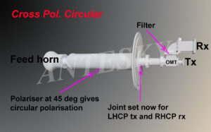
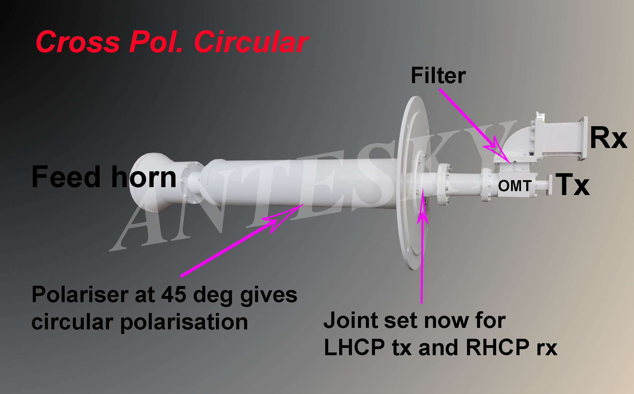
The diagram of feed network
These images below may help. Imagine the feed systems are lying flat on a table and you are looking directly downwards at them. Upwards, vertical, is directly towards you from the centre of the image.
Note that there is a feed horn on the left, then a polariser tube, then a diplexer joint or OMT, then the LNB and BUC.
If the polariser is removed, or oriented so the line of pins are uppermost, the feed becomes a linear polarisation feed.
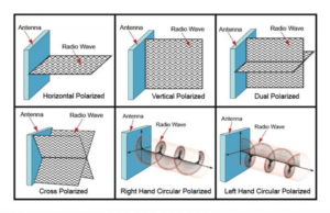
When it is found that the signal cannot be received or is unstable during the test, please consider checking the feed system first. Whether the contact is bad, adjust the polarization, usually there is no change when the polarization is turned ±45 degrees, but it will change when it is turned 90 degrees, please try to turn it around. Please also try another satellite. If the signal does not change after the operation, please proceed to the next step to check the HPA.
- HPA(High power amplifier)
A high power amplifier is a non-linear device which amplifies a small signal to a significant level, which is to make the carrier transmitted by the earth station reach the specified EIRP value.
Generally HPA , with a wide frequency band, will produce noise and spurious wave to affect receiving signal. Under this condition, you can add a filter on the Tx. Port and have a try. Another way is to use the HPA monitoring port and TLT output port to check the HPA output port. If there is no noise on the spectrum analyzer, then eliminate the HPA problem. The next step is to test the isolation of the cross-polarized port.
- XPD(Cross polarization discrimination)
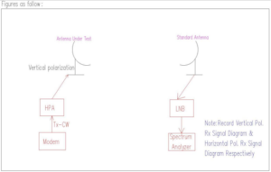
The diagram of cross polarization isolation
Firstly, the following serves to build an understanding about the antenna parameter known as Cross Polar Discrimination (XPD). It is important for a low level of correlation between the orthogonally polarized propagation channels. The requirements for microwave antennas are significantly higher (20 to 30 dB). the normal standard is not less than 35dB for linear polarized antenna, and axis ratio not more than 1.06dB for circular polarized antenna.
Put simply, cross polar discrimination is a measure of how polar an antenna element is and used measure the rejection of an orthogonally polarised transmission. A high XPD figure means a cleaner signal in colocated transmission environments.
The cross polar discrimination is defined as the ratio of the cross-polarized signal component from one transmitted polarization to the copolarized signal component for the orthogonal transmitted polarization. The two signal components that determine cross-polarization isolation are received on the same polarization.
In the process of verifying the network access of the transmitting antenna to the satellite, the polarization isolation is a very important indicator. If this index does not meet the standard, which not only makes the transmission signal in the positive polarization direction suffer from polarization reduction, but also reverse it. The polarization leakage signal will interfere with the service on the reverse polarization frequency band. For the receiving antenna, the polarization isolation index is unqualified, and the antenna will receive a strong reverse polarization service signal while receiving the positive polarization service, which will interfere with the positive polarization reception signal and affect the quality of the reception service. Therefore, whether it is an uplink transmitting antenna or a downlink receiving antenna, the precise adjustment of polarization isolation is very important and necessary. So how to measure XPD, here we provide a single carrier test method.
Test Procedure of XPD based on single carrier testing method
*Tools: 2 sets of antennas, one is under testing antenna, the other is standard reference antenna; spectrum analyzer
* Method: Comparison
* Antenna preparation
- Antenna under test : “4.8m Cross Pol. Antenna”
- Used for transmit single carrier (Tx-CW(please refer to the below appendix)), for example, transmit“Vertial Polarization wave”.
Notes: please refer the appendix for the method of setting satellite modem Tx-CW mode.
- Standard antenna
- Prepare a standard antenna.
* Calibration of “standard antenna”
- Use the “standard antenna” to align the satellite to receivethe satellite signal, and adjust the signal to the maximum in the vertical direction;
- Rotate the polarization of the “standard antenna” by 90° ( that is horizontal polarization), and check whether there is a signal from the reverse polarization (horizontal polarization) of the “standard antenna”. If there is a signal, please adjust the signal to the minimum;
- Adjust the polarization of the “standard antenna” to vertical polarization, and adjust the satellite signal to the maximum;
- Repeat step (2).
- Until the vertical polarization received signal of the “standard antenna” is adjusted to the maximum, and the horizontal polarization signal is adjusted to the minimum at the same time.
Note: The vertical polarization of Rx frequency is different from the horizontal polarization of Rx frequency, please refer to the satellite frequency of the satellite company.
* Test process
(1) Use the “standard antenna” to find unused frequency on the vertical polarization, here in this step you need to communicate with satellite company in advance; and then calculate the transmit frequency of the “test antenna” on the vertical polarization based on the receive frequency.
(2) The “antenna under test” transmits a single carrier with vertical polarization.
(3) Use the calibrated “standard antenna” to receive the vertical single carrier from the “antenna under test” with vertical polarization (take a photo as picture 1)
(4) Rotate the polarization of the “standard antenna” from vertical receive to horizontal receive until the horizontal receive signal of the “standard antenna” is the smallest (take a photo as picture 2)
(5) The signal difference between picture 1 and picture 2 is the cross-polarization isolation.
Note: During the test, pay attention to the “standard antenna” receive, the level reference value of the spectrum analyzer should be adjusted to the same.
* Some cautions during testing.
- Check whether the feed is co-polarized or cross-polarized
- Check whether the satellite is a co-polarized satellite or a cross-polarized satellite
- The field test is generally tested by the comparison method
- The tested antenna transmits a single carrier
- Prepare another antenna as standard reference antenna to receive
- The polarization of the other receiving antenna should be adjusted in advance, especially the reverse polarization, to ensure that there is no signal from the reverse polarization.
The receiving antenna receives the single carrier of the antenna under test, and the difference value between the maximum value and the minimum value (reverse polarization) is the cross-polarization isolation.
We hope you can learn how to test XPD from above description. Please talk with us via sales@antesky.com of you have any question about it. Thanks.
Appendix
How to set satellite modem Tx-CW mode?
- Set satellite modem LOCAL mode.
- Find the unused frequencyof satellite transponder through satellite company and spectrum analyzer.
- Calculate the Rx frequency by Tx frequency.
- Set satellite modem
- Set Tx-CW mode in the satellite modem.
- Set Tx frequency, and set Rx frequency at the same time.
- Set HPA Tx power (-30db), and increase gradually.
Remember not to use too much transmission power.
- Turn on Tx switch.
For cross pol, Transmit V & Receive H.
Satellite used must be cross pol satellite. Co-pol satellite can’t be used.
Set satellite modem according to the description above .
- If transmission is vertical, and the spectrum analyzer will have the following signals in the horizontal direction (Reference Picture)
- Rotate the Receive Pol (Rotate from H to V) – How will the signal change?
Please send video of rotating receive. According to the provided data, calculate whether the cross-polarization isolation is greater than 30db.

