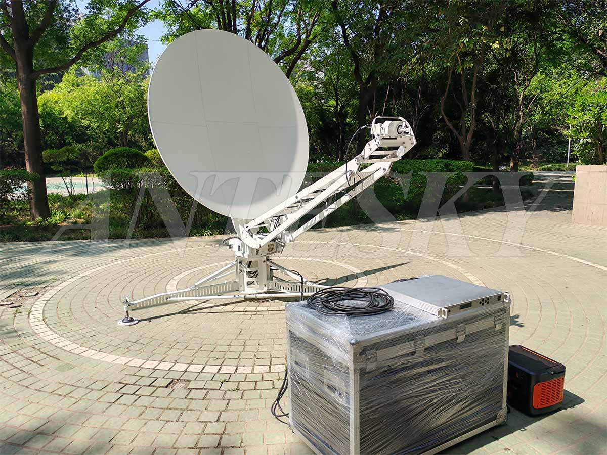
Previously, we listed on website that various 1.8m ka band flyaway antenna projects, which are manually drive mode. Today, let us introduce Antesky 1.8m automatic flyaway antenna with Ka band and we will focus on the installation and testing of this antenna. Please go ahead for the detailed introduction.
1 Product features of 1.8m Ka band automatic flyaway antenna
a) Easy disassembly and assembly, stable structure, superior performance, quicksatellite
b) The configured GPS has high accuracy and the electronic compass has strong anti-interference performance, ensuring the stability and accuracy of the satellite alignment function.
c) The antenna’s automatic satellite aligningdoes not exceed 3 minutes (RMS).
d) Multiple protection functions such as automatic warning, mechanical limit, and software limit, making the antenna operation safer.
2. Product compositionof 1.8m Ka band automatic flyaway antenna
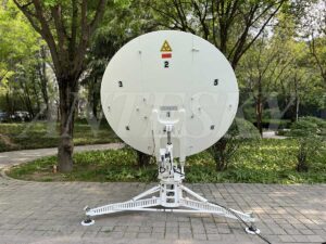
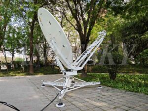
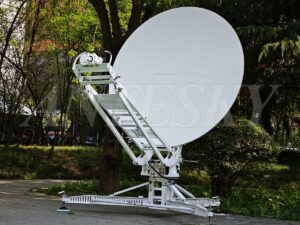
-As you can see that 1.8m Ka band automatic flyaway antenna is mainly composed of turntable pedestal, support legs, back structure, support arm and motorized EL push rod ,Gregorian dual-reflector offset feed etc. Antenna control subsystem includes azimuth, elevation, polarization motor.
-Antenna tracking subsystem contains beacon receiver, angle sensor, GPS, WiFi module, ATPC control board.
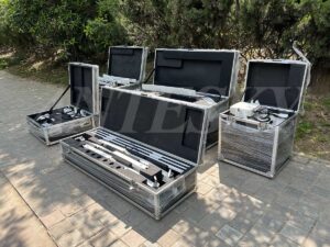
-Antenna is packed with rigid carbon fiber cases with wheels, which makes easier to moveable and deployable during installation.
1.8m Ka band automatic flyaway antenna rear view
1.8m Ka band automatic flyaway antenna front view
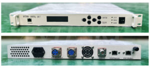
1.8m Ka band automatic flyaway antenna controller
1.8m ka band automatic flyaway antenna is packed in 5 carbon fiber cases
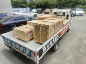
Outer packed with wooden cases for prevent the shaking and damage during transportation
3. Installation steps of 1.8m Ka band automatic flyaway antenna
There are total 8 steps for assembly and installation of 1.8m Ka band automatic flyaway antenna. 2 persons will cooperate during installation. Details are shown below. Also you can click the installation video of 1.8m Ka band automatic flyaway antenna.
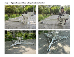
Step 1: 3 pcs of support legs with pull rods installation
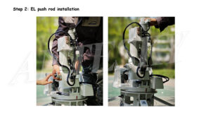
Step 2: EL push rod installation
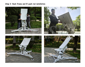
Step 3: Back frame and El push rod installation
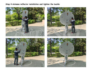
Step 4: Antenna reflector installation and tighten the buckle
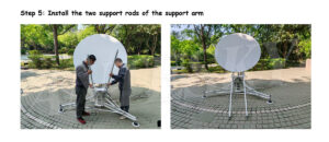
Step 5: Install the two support rods of the support arm
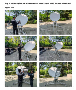
Step 6: Install support arm of feed bracket (down & upper part), and then connect with support rods
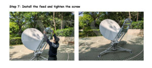
Step 7: Install the feed and tighten the screw
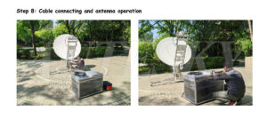
Step 8: Cable connecting and antenna operation
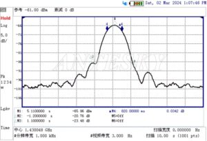
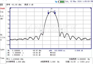
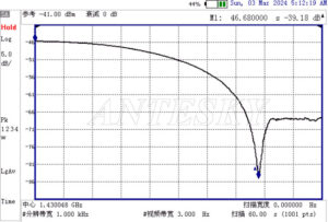
- Test radiation patterns of 1.8m Ka band automatic flyaway antenna
20.68GHz AZ
20.68GHz EL
Cross polarization isolation
Above is the brief introduction of 1.8m antenna installation and testing. Apart from 1.8m ka band flyaway antenna, 0.75m-2.4m flyaway antenna are our mature items as well. Please refer to this product page of Antesky flyaway antennas.
If you are looking for such antenna, please contact with us directly via sales@antesky.com. Thanks!

