With the emergence of commercial aerospace and the development of 5G technology, the satellite frequency resources requirements and data transmission bandwidth and speed have become increasingly important. In this time, X band can meet to meet new requirements of higher wireless communication frequency bands for satellite operators.
- Introduction and application of X band
X-band refers to the frequency band operating in the 7-12 GHz range. X-band has the advantages of high signal-to-noise ratio, low power consumption and high anti-interference capability. Its applications mainly include:
- Radar Systems: X band is extensively used in radar systems for various purposes such as weather monitoring, air traffic control, maritime surveillance, and military applications. Its shorter wavelength allows for better resolution and accuracy in target detection and tracking.
- Satellite Communications: X band is utilized for satellite communications, including satellite broadcasting, satellite internet services, and military satellite communications. Its relatively high frequency enables higher data transfer rates compared to lower frequency bands.
- Remote Sensing: X band is employed in remote sensing applications such as environmental monitoring, agriculture, forestry, and geological surveys. Its ability to penetrate through foliage and clouds makes it suitable for certain remote sensing applications.
- Navigation Systems: X band is used in various navigation systems, including marine and aviation radar systems, as well as in GPS augmentation systems for improved accuracy.
- Scientific Research: X band is utilized in scientific research applications such as radio astronomy for studying celestial objects and phenomena.
- Military Applications: X band is extensively used in military applications for radar systems, communication, electronic warfare, and missile guidance systems due to its ability to provide high-resolution imaging and target discrimination.
Overall, the X band’s characteristics make it suitable for a wide range of applications that require high resolution, accuracy, and data transfer rates.
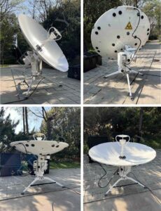
This January, customer ordered 1 set of 1.2m automatic flyaway antenna with X band (Rx.: 7.25~7.75GHz; Tx.: 7.9~8.4GHz) from Antesky. And we’d tested and debugged in our factory. Below we will show you further detailed introduction about this antenna.
Antesky 1.2m automatic flyaway antennas
1.2 Product characteristics of 1.2m automatic flyaway antenna with X band
a) Convenient operation, stable structure, rapid satellite search time, and high security;
b) Carbon fiber composite materials reflector is formed with at one time, with high accuracy, high strength, light weight, and easy disassembly;
c) Three legs tripod with high wading depth and strong wind resistance;
d) Modular design for easy maintenance and function expansion
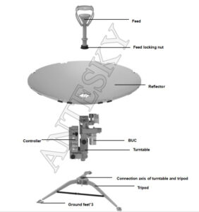
1.3 Composition of 1.2m automatic flyaway antenna with X band
Schematic diagram of 1.2m automatic flyaway antenna with X band structure
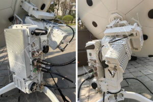
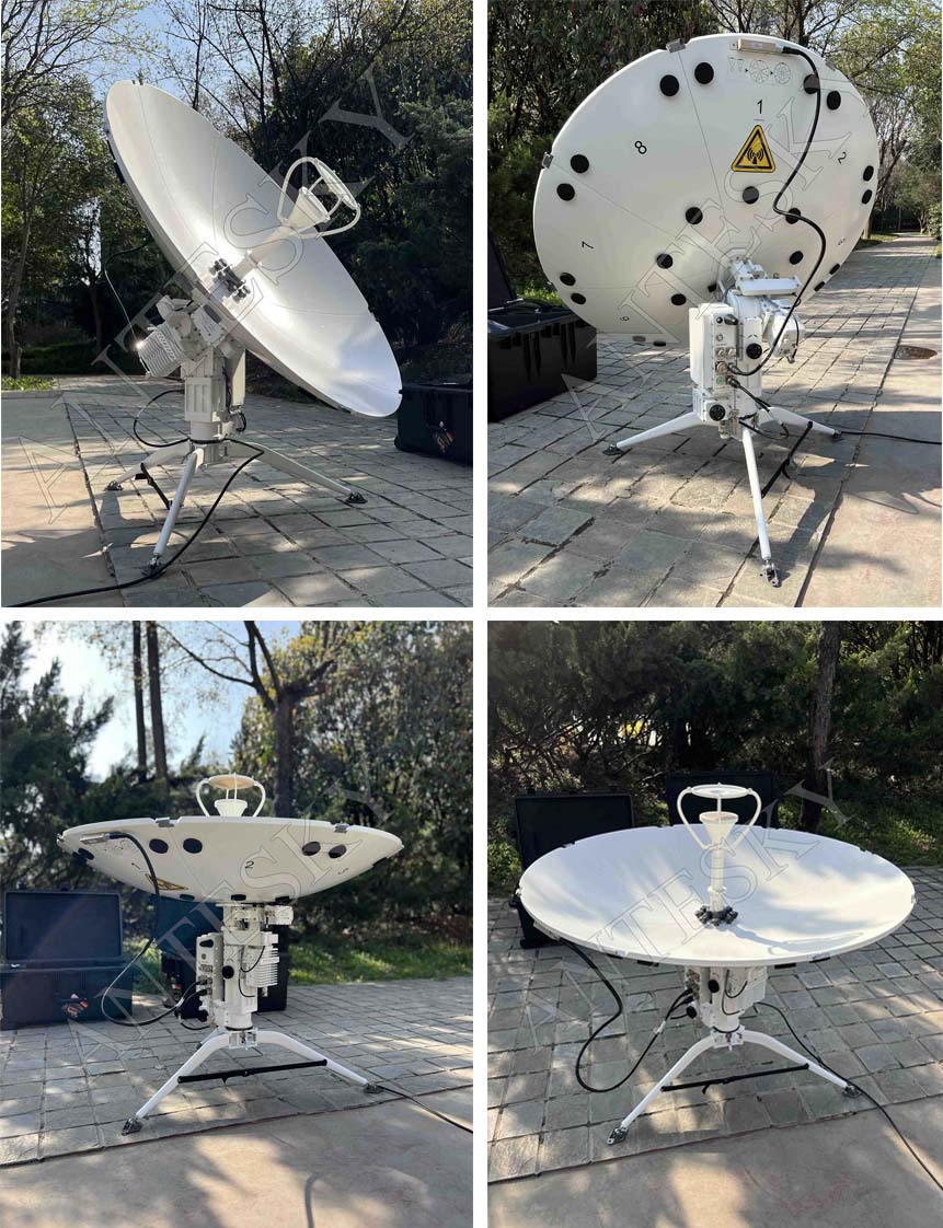
1.2m automatic flyaway antenna& pedestal system display
Hand held phone controller
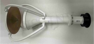
X band feed system of 1.2m automatic flyaway antenna with X band
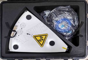
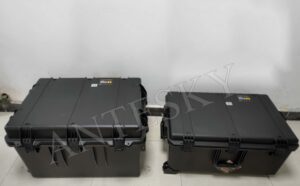
The 1.2m automatic flyaway antenna with X band is packed in 2 pelican cases, which are labeled 2-1 and 2-2. The distribution of the antenna components inside is listed fro below table.
Pelican case of 1.2m automatic flyaway antenna with X band
1.4 Installation steps of 1.2m automatic flyaway antenna with X band
There are total 4 steps for installation and assembly.
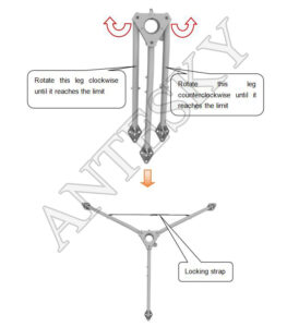
Step 1: unfold the tripod of 1.2m automatic flyaway antenna with X band
First, open the legs on both sides of the tripod to the limited position; then, connect and tighten the locking straps.
Tripod deployment process diagram
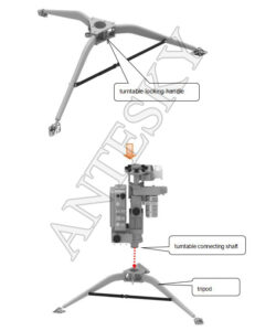
Step 2: Turntable installation of 1.2m automatic flyaway antenna with X band
Open the turntable locking handle and put the turntable on the tripod;
Diagram of turntable installation
Step 3: Antenna reflector installation of 1.2m automatic flyaway antenna with X band
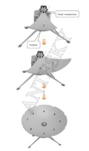
according to the markings on the back of the antenna surface, install the 8 antenna panels onto the center plate of the antenna reflector in sequence and lock the buckles.
Diagram of antenna reflectors assembly
Step 4: Feed installation of 1.2m automatic flyaway antenna with X band
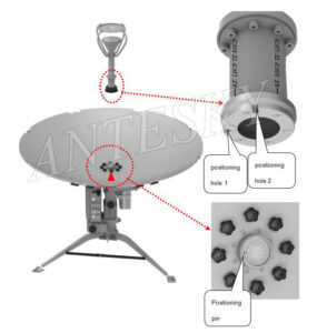
Align the positioning hole at the bottom of the feed with the positioning pin on the upper part of the feed support, and insert it.
Feed installation diagram
1.5 Test radiation patterns of 1.2m automatic flyaway antenna with X band
As we mentioned our 1.2m X band automatic flyaway antenna is with highly electrical performance. You can check the below patterns further.
Radiation pattern@8.1GHz
Radiation pattern@7.5GHz
The 1.2-meter flyaway antenna is one of our advantageous products, including manual and automatic drive modes. For details, please click on the product page. As the new trend band in the satellite communication industry, we are also committed to further research on X-band. Among them, we have now developed the latest C/KU/X integrated OMT system for fixed station antennas. Please click to learn more.
We believe you learn something useful from above brief introduction of X band and our 1.2m automatic flyaway antenna with X band. Welcome to inquiry us if you arelooking for such high quality antenna with the best price. Our email sales@antesky.com.

